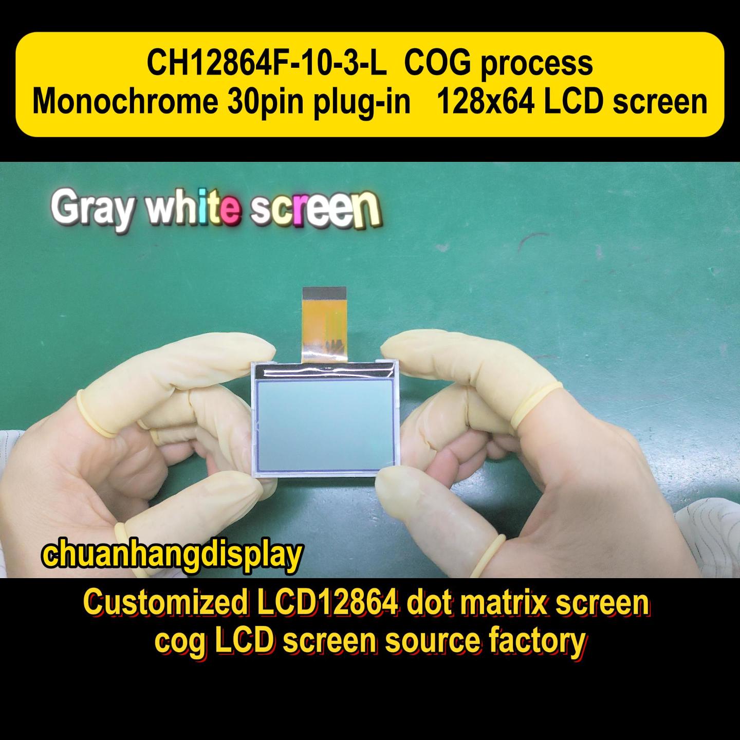
Selecting display components for robust, space-constrained electronic devices requires a thorough understanding of underlying packaging technologies. For product designers and sourcing engineers in the industrial, medical, and automotive sectors, selecting a COG LCD Screen for high-reliability applications requires a deep understanding of display architecture. This technology, which directly mounts the display driver integrated circuit (IC) onto the glass substrate, offers significant advantages in footprint reduction, weight, and power efficiency compared to traditional packaging methods.
This comprehensive guide analyzes the structural design, material compositions, manufacturing parameters, and supplier selection strategies necessary for successful display integration.
To understand why this display architecture is selected for modern electronic designs, it is useful to compare it with alternative packaging methodologies: Chip-on-Board (COB) and Chip-on-Flex (COF).
+-------------------------------------------------------------+
| COB (Chip-on-Board)                                         |
| [LCD Glass] <== Elastomer/Pins ==> [PCB with Epoxy IC]     |
+-------------------------------------------------------------+
| COF (Chip-on-Flex)                                          |
| [LCD Glass] <==================== [Flexible Circuit with IC]|
+-------------------------------------------------------------+
| COG (Chip-on-Glass)                                         |
| [LCD Glass with Integrated Driver IC] <=== [FPC Connection] |
+-------------------------------------------------------------+In COB architecture, the driver IC is mounted directly onto an external printed circuit board (PCB) and covered with a protective epoxy resin ("black blob"). The electrical connection between the PCB and the liquid crystal display panel is typically established using elastomeric connectors (commonly called zebra strips) or metal pins.
Disadvantages: This method increases the overall thickness, weight, and component count of the display module, making it less suitable for compact, handheld designs.
COF technology involves mounting the driver IC onto a flexible printed circuit (FPC), which is then bonded to the display glass.
Disadvantages: While COF offers flexibility and allows for thinner borders, the manufacturing process is complex, and the flexible substrate is more susceptible to damage during assembly and handling.
The primary structural characteristic of a COG LCD Screen is the elimination of the bulky printed circuit board and the separate IC packaging. The bare silicon driver chip is mounted directly onto the peripheral ledge of the display's glass substrate. Conductive tracks on the glass connect the chip output pads to the display pixels, while input tracks lead to the edge of the glass where a flexible printed circuit or connector is attached. This configuration significantly reduces the profile and mass of the display module.
The performance and durability of the display module depend on the materials used in its construction. Understanding these materials helps engineers specify the correct display parameters for challenging operating environments.
The foundation of the display is composed of two sheets of glass: the thin-film transistor (TFT) or passive matrix backplane and the color filter or front plane glass.
Soda-Lime Glass: Commonly used in cost-sensitive, standard-temperature applications.Borosilicate Glass: Specified for high-reliability industrial and automotive displays due to its superior thermal resistance, optical clarity, and resistance to chemical degradation. Glass thickness typically ranges from 0.4 mm to 1.1 mm, with thinner substrates chosen for lightweight portable devices.
Indium Tin Oxide is a transparent, highly conductive metal oxide deposited onto the glass substrate via physical vapor deposition (sputtering). The ITO layer is photolithographically etched to form the electrodes that control individual pixels, as well as the trace lines connecting the driver IC to the active display area. The sheet resistance of the ITO layer—typically measured in ohms per square (Ω/□)—must be carefully balanced; lower resistance improves signal integrity over larger display areas but requires thicker, less transparent coatings.
ACF is the primary adhesive and electrical medium used to bond the driver IC to the glass substrate. It consists of a thermoplastic or thermosetting epoxy resin matrix filled with microscopic conductive particles.
Particle Structure: These particles are typically polymer spheres plated with nickel and gold, ranging from 3 to 5 micrometers in diameter.Mechanism: During the thermocompression bonding process, vertical pressure deforms the particles between the chip bumps and the ITO pads, establishing electrical conductivity in the Z-axis. Meanwhile, the uncompressed particles suspended in the cured resin maintain electrical insulation in the X and Y axes, preventing short circuits between adjacent fine-pitch pads.
| Component | Common Materials | Sourcing Considerations |
| Glass Substrate | Borosilicate, Soda-Lime | Thermal expansion coefficient, thickness tolerance |
| Conductive Traces | Indium Tin Oxide (ITO) | Sheet resistance (Ω/□Ω/□), transmission rate |
| Bonding Medium | Anisotropic Conductive Film (ACF) | Particle size, curing temperature, shelf life |
| Driver IC | Silicon Die (with Au bumps) | Pitch size, drive capability, power consumption |
The assembly of a high-quality display requires highly controlled, automated manufacturing environments. The mechanical integrity of a COG LCD Screen relies heavily on the quality of the glass edge and the bonding tape. Display manufacturers like Chuanhang Display utilize specialized precision alignment systems to register the driver chip bumps to the ITO pads on the glass.
[ Thermode / Bonding Tool (Heat + Pressure) ]
                        |||
                  [ Driver IC Die ]
                  [ Gold Bumps ]
      =================================== <--- ACF (with conductive particles)
      ----------------------------------- <--- ITO Pad Layer
              [ Glass Substrate ]
The assembly workflow consists of several distinct stages:
Surface Preparation and Cleaning: The glass substrate and bare silicon dies undergo multi-stage ultrasonic cleaning and plasma surface treatment. This removes organic contaminants, improves surface energy, and ensures optimal adhesion of the ACF.ACF Pre-Application: The ACF tape is cut to precision and pre-applied to the bonding area of the glass substrate under low heat and pressure.Alignment: Vision systems with sub-micron resolution align the gold bumps on the driver IC with the corresponding ITO terminal pads on the glass. Even slight misalignments can lead to open circuits or high contact resistance.Thermocompression Bonding: A heated bonding tool (thermode) applies a precise profile of temperature (typically 150∘C150∘C to 200∘C200∘C) and pressure (typically 4040 to 80 MPa80 MPa) for a specified duration (usually 5 to 15 seconds). This cures the epoxy matrix and traps the conductive particles to form reliable electrical contacts.FPC Bonding: After the IC is mounted, the input Flexible Printed Circuit is bonded to the peripheral glass traces using a similar ACF process, providing the physical interface to the system motherboard.Encapsulation: A specialized silicone or UV-curable epoxy sealant is applied over the exposed silicon die and the FPC junction. This encapsulation layer protects the assembly from moisture, atmospheric pollutants, and mechanical vibration.
Designing and deploying displays in rugged environments presents several technical challenges. Engineers must evaluate how display manufacturers address these vulnerabilities during design and production.
Silicon, glass, and copper FPCs have different coefficients of thermal expansion (CTE). Under extreme temperature cycling, these material differences generate mechanical shear stress at the bonding interface, which can lead to micro-cracking of the ACF joint and intermittent display failure. At Chuanhang Display, manufacturing protocols involve rigorous thermal shock testing and mechanical shear tests to ensure that the material pairings and bonding profiles withstand industrial temperature ranges (typically−30∘C−30∘C to +85∘C+85∘C).
Because the driver IC is mounted directly onto the glass substrate and connected via fine-pitch ITO lines, it is highly sensitive to ESD during assembly and handling. Glass is an insulator and can accumulate static charge easily.
Mitigation: Manufacturing facilities must use ionization bars, conductive wrist straps, and ESD-safe trays. At the system level, display interfaces should incorporate transient voltage suppressors (TVS) to protect the display driver from ESD pulses.
In industrial machinery or automotive dashboards, displays are subjected to continuous vibration. If the FPC connection or the driver IC encapsulation is insufficiently reinforced, the bonded joints can detach. Designing a rigid bezel and incorporating dampening gaskets (such as polyurethane foam or silicone) around the display module helps distribute mechanical stresses away from the glass edges.
The space savings and reliability of these display modules make them highly suitable for a wide range of demanding applications.
+-----------------------------------------------------------------+
|               COG LCD Screen Applications                       |
+---------------------+---------------------+---------------------+
|     Industrial      |       Medical       |     Automotive      |
|    Instruments      |       Devices       |     Sub-Systems     |
|                     |                     |                     |
| * Flow Meters       | * Infusion Pumps    | * Climate Control   |
| * Handheld Tools    | * Pulse Oximeters   | * Digital Clocks    |
| * Grid Monitors     | * Glucose Meters    | * EV Charger Panels |
+---------------------+---------------------+---------------------+Field instruments, such as handheld multimeters, flow meters, and environmental sensors, operate under strict power and space limitations. When integrating a COG LCD Screen into a portable medical device or an outdoor metering system, engineers must account for the display's optical performance. The direct-bond architecture allows for high-density segment or dot-matrix displays that fit within small enclosures without adding unnecessary weight.
Medical devices, including automated infusion pumps, glucose monitors, and portable pulse oximeters, require clear readability and reliable performance. The flat profile of the display module simplifies the sealing of the front panel, helping to prevent dust and fluids from penetrating the enclosure during sanitization.
Sub-displays in vehicle dashboards, climate control panels, and marine depth finders operate under direct sunlight and extreme temperatures. Using FSTN (Film-compensated Super-Twisted Nematic) liquid crystal materials with polarizer films ensures wide viewing angles and high contrast ratios across varying lighting conditions.
Sourcing a custom COG LCD Screen involves navigating both technical specifications and long-term commercial supply chains. Because the tooling costs (Non-Recurring Engineering, or NRE) for custom glass and FPC designs can be significant, selecting the right partner is vital.
A professional display supplier must offer extensive customization options, including:
Custom segment patterns or specific dot-matrix resolutions.Tailored FPC lengths, shapes, and connector pinouts to match existing system architectures.Integrated backlight options (LED color, brightness levels, and light-guide configurations).Custom polarizer selections (transmissive, reflective, or transflective for outdoor viewability).
Industrial products often require production lifecycles exceeding 7 to 10 years. Unlike the fast-moving consumer electronics market, industrial display suppliers must guarantee the long-term availability of key components, particularly the driver IC. Sourcing managers should verify that the display supplier has strong relationships with IC foundries and can offer drop-in replacements or secure last-time-buy inventories if a specific driver is phased out.
A qualified vendor should provide comprehensive verification data, including:
High/Low-Temperature Storage and Operation Tests: Verifying display performance under thermal extremes.Constant Humidity and Damp Heat Testing: Ensuring the ACF bond and encapsulation resist moisture penetration.Vibration and Drop Testing: Simulating shipping and harsh operational environments.Optical Measurements: Detailing response times, contrast ratios, and viewing cones.
A1: The lifespan of the display is primarily determined by the stability of the liquid crystal material, the quality of the polarizers, and the degradation of the LED backlight. In outdoor environments, standard polarizers can degrade under continuous ultraviolet (UV) exposure. By specifying UV-compensated polarizers and using high-grade sealing epoxies, a high-quality display can achieve an operational lifespan exceeding 50,000 hours. This performance is supported by protective top glass and appropriate UV filtering.
A2: No. Because the silicon driver IC is bonded directly to the glass substrate using a cured thermosetting ACF, removing the chip requires temperatures that typically damage the delicate ITO electrodes on the glass. Therefore, if a driver IC fails, the entire display module must be replaced. This highlights the importance of using robust static prevention and electrical overstress protection during handling and operation.
A3: For a custom display, the Non-Recurring Engineering (NRE) tooling cost typically covers the photolithographic masks for the custom glass layout, the FPC design, and the backlight housing tool. Depending on the size and complexity of the module, NRE costs generally range from $1,500 to $5,000 USD. The initial design and sample phase usually takes 4 to 6 weeks, while mass production lead times typically range from 8 to 12 weeks after sample approval.
A4: At lower temperatures, the viscosity of the liquid crystal material increases, which slows down the relaxation and alignment of the LC molecules. This results in longer response times and visible ghosting at sub-zero temperatures. To mitigate this in cold-weather applications, engineers can specify wide-temperature liquid crystal formulations, utilize built-in transparent ITO heaters on the glass, or choose driver ICs with temperature-compensation circuits.
A5: Reflective polarizers use ambient light to illuminate the display, making them highly power-efficient and legible in direct sunlight, though unusable in dark environments without an front-light. Transmissive polarizers require a continuous backlight to be readable and are ideal for indoor environments with low ambient light. Transflective polarizers combine characteristics of both; they reflect ambient light in bright conditions and transmit backlight in dark settings, offering a balanced solution for varying outdoor and indoor lighting conditions.
Integrating a customized display module requires close collaboration between electrical, mechanical, and sourcing teams. Interested parties are encouraged to contact Chuanhang Display for technical consultations, detailed engineering drawings, and samples. Our engineering team is available to assist you in optimizing your display configuration, specifying appropriate materials, and ensuring seamless integration into your end product.