High-reliability industrial instrumentation, medical equipment, and smart utility meters require display panels that withstand harsh operational environments while maintaining optimal legibility. While high-resolution color thin-film transistor (TFT) panels are common in consumer electronics, monochrome liquid crystal displays (LCDs) remain the standard for applications prioritizing low power consumption, high contrast, and long-term durability. To meet these rigorous demands, sourcing teams must carefully evaluate technologies from prominent manufacturers, including solutions produced by manufacturers like SINDA. As a trusted distributor and technical integrator, Chuanhang Display helps industrial buyers navigate these manufacturing standards to identify the optimal match for their hardware specifications.
This guide provides a detailed technical analysis of monochrome display construction, panel materials, common integration challenges, and procurement strategies to assist engineers and purchasing professionals in making informed decisions.
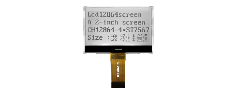
Monochrome LCDs operate on the principle of light polarization controlled by liquid crystal alignment. Understanding the distinct visual characteristics of SINDA displays requires examining the underlying liquid crystal modes, each offering unique performance trade-offs regarding response time, viewing angles, and thermal stability.
TN panels are the most common and cost-effective option available. The liquid crystal molecules undergo a 90-degree twist between the glass substrates.
Viewing Angles: Typically limited to 45 to 60 degrees.Contrast Ratio: Generally ranges from 5:1 to 10:1.Best Suited For: Direct-drive segment displays in utility meters, handheld battery-operated devices, and simple kitchen appliances.
HTN technology increases the liquid crystal twist angle to approximately 100 to 120 degrees.
Viewing Angles: Offers a wider viewing angle than standard TN (up to 80 degrees).Contrast Ratio: Slightly improved contrast, typically 10:1 to 15:1.Best Suited For: Industrial scales, power supplies, and simple environmental controllers requiring modest off-axis viewing.
STN displays utilize a twist angle ranging from 180 to 270 degrees. This high twist angle results in a steeper electro-optical transfer curve, allowing for high-multiplex driving schemes.
Visual Appearance: Yellow-green or gray background with dark blue pixels, or blue background with white pixels.Multiplexing: Highly suited for complex dot-matrix graphics and character displays.Viewing Angles: Up to 120 degrees horizontal.
To address the background coloration inherent to STN technology, FSTN panels incorporate an optical compensation film laminated to the outer surface of the glass.
Visual Appearance: A clean black-and-white display.Contrast Ratio: Ranging from 30:1 to 50:1.Best Suited For: High-end medical diagnostic equipment, marine instrumentation, and complex industrial control panels.
Vertical Alignment technology represents a major step forward in contrast ratio and viewing angle performance. Under zero-voltage conditions, the liquid crystal molecules align perpendicular to the glass substrates, blocking almost all light.
Contrast Ratio: Frequently exceeds 500:1, often reaching 1000:1.Viewing Angles: Near-isotropic viewing angles of up to 160 degrees in all directions.Visual Appearance: True black background with high-contrast, customizable segment colors (achieved via color silk-screen printing on the backlight or custom LED selection).
The long-term reliability of an industrial display module is directly tied to the raw materials chosen during the manufacturing phase. A mismatch between the operational environment and display materials can lead to premature field failures.
+-------------------------------------------------------------+
| Top Polarizer |
+-------------------------------------------------------------+
| Top ITO Glass |
+-------------------------------------------------------------+
| Liquid Crystal Fluid (TN / STN / FSTN / VA) |
+-------------------------------------------------------------+
| Bottom ITO Glass |
+-------------------------------------------------------------+
| Bottom Polarizer |
+-------------------------------------------------------------+
| LED Backlight Unit |
+-------------------------------------------------------------+
The operating temperature range of an LCD is dictated by the clearing point (the temperature at which the liquid crystal fluid transitions into an isotropic liquid) and the freezing point of the fluid.
Standard Temperature: 0°C to +50°C (suitable for indoor consumer devices).Wide Temperature: -20°C to +70°C (suitable for typical industrial control environments).Ultra-Wide Temperature: -30°C to +80°C or -40°C to +85°C (required for outdoor infrastructure, automotive clusters, and aerospace applications).At lower temperatures, the viscosity of the fluid increases, which slows down the response time. Utilizing specialized wide-temperature fluids ensures that the pixels transition fast enough to prevent text smear.
Polarizers are highly sensitive to moisture and heat. Under high-humidity conditions, low-grade polarizer adhesives can hydrolyze, leading to peeling, bubbling, and depolarization.
Reflective Polarizers: These feature a reflective backing on the bottom polarizer. They reflect ambient light, making them highly legible in direct sunlight without a backlight, which minimizes power consumption.Transmissive Polarizers: These require a backlight to be readable. They are ideal for low-light or indoor environments but offer poor outdoor visibility when the backlight is off.Transflective Polarizers: These combine both reflective and transmissive properties. They reflect ambient sunlight while allowing backlight transmission in dark conditions, offering excellent versatility.Anti-UV Treatment: For outdoor installations, specifying polarizers with an integrated UV protection layer prevents the polarizers from turning yellow or brown under constant solar radiation.
The conductive ITO layer sputtered onto the glass substrates must have highly uniform sheet resistance (typically measured in ohms per square).
Glass Thickness: Standard industrial displays utilize 1.1mm or 0.7mm soda-lime glass. For applications requiring extreme shock resistance, chemically strengthened aluminosilicate glass can be specified.Line Pitch and Spacing: As segment density increases, narrower ITO trace widths are required. Proper etching processes prevent short circuits and capacitive coupling between adjacent traces.
The selection of the LED dies and the light guide plate (LGP) determines the brightness uniformity and half-brightness lifetime of the display.
Half-Brightness Lifetime: Industrial-grade backlights should be rated for a minimum of 50,000 hours of continuous operation at 25°C.Thermal Management: Incorporating adequate heat dissipation paths within the bezel design is vital, as excessive heat accelerates LED lumen degradation and shifts the color point.
When integrating a SINDA customized panel, design engineers frequently encounter electrical and mechanical integration challenges. Understanding these failure modes allows teams to implement preventative design practices.
In high-multiplex STN or FSTN designs, non-selected segments may partially activate, appearing as a faint "ghost" image. This occurs when the driving voltage (Vlcd) is not optimized, or when the multiplex duty cycle exceeds the performance threshold of the liquid crystal fluid.
Technical Mitigation:Adjust the bias ratio on the display driver IC to match the liquid crystal threshold voltage curve.Implement temperature compensation circuitry (either thermistor-controlled or register-based) to dynamically adjust Vlcd as ambient temperatures shift.
Monochrome displays are often located on the exterior of a device, making them vulnerable to electrostatic discharge from user interaction. Additionally, long flat-flex cables (FFC) can act as antennas, radiating EMI or picking up noise from nearby switching power supplies.
Technical Mitigation:Incorporate transient voltage suppressor (TVS) diodes on all signal lines entering the LCD interface.Ground the metal bezel of the LCD module to the chassis ground through low-impedance copper foil or conductive gaskets.Utilize shielded FFCs with grounded hatch patterns to isolate high-frequency data lines.
In applications where operators view the screen from below or above (such as wall-mounted controllers or low-positioned machinery), the contrast of standard TN or STN panels can degrade significantly.
Technical Mitigation:Specify the viewing direction (6 o'clock or 12 o'clock) during the design phase to align the display’s optimum viewing cone with the user's line of sight.Transition to VATN technology if wide viewing angles are required across all four quadrants.
To aid in the selection process, the following table compares the physical, optical, and cost characteristics of the primary monochrome technologies discussed.
| Technology | Contrast Ratio | Max Viewing Angle | Operating Temp Range | Power Consumption | Relative Tooling Cost | Primary Application |
| TN | 5:1 – 10:1 | 60° | -30°C to +80°C | Lowest | Low | Basic utility meters, digital clocks |
| HTN | 10:1 – 15:1 | 80° | -30°C to +80°C | Low | Low | Handheld test equipment, scales |
| STN | 15:1 – 30:1 | 120° | -35°C to +85°C | Medium | Medium | Dot-matrix CNC controllers |
| FSTN | 30:1 – 50:1 | 140° | -35°C to +85°C | Medium | Medium | Medical monitors, outdoor GPS |
| VATN | 500:1 – 1000:1 | 160° | -30°C to +85°C | High (backlight needed) | High | Automotive dashboards, high-end audio |
Procuring customized monochrome LCDs involves unique engineering and supply chain considerations. Unlike standard off-the-shelf components, custom segment or dot-matrix displays require upfront engineering investments and careful life-cycle management.
When off-the-shelf character or graphic modules do not align with the user interface requirements, custom tooling is necessary. The customer provides a drawing indicating the required icons, seven-segment digits, and active area dimensions.
Photomask Creation: The manufacturer creates photomasks to etch the ITO patterns onto the glass.Bezel and Light Guide Design: Custom metal bezels and plastic light guides are developed to secure the display assembly and fit the host housing.
[ Custom Segment Layout Definition ]
│
▼
[ Photo-mask & ITO Etching ]
│
▼
[ Interconnection Assembly: Pins, Zebra, COG ]
│
▼
[ Environmental Burn-in Testing ]
The method used to connect the LCD glass to the driver PCB significantly impacts the durability, thickness, and cost of the module:
Metal Pins: Conductive pins are clipped and epoxy-bonded to the glass edge. These pins solder directly into the PCB holes, providing a highly vibration-resistant connection.Elastomeric Connector (Zebra Strip): Alternating layers of conductive and non-conductive silicone are compressed between the glass contacts and the PCB traces. This solderless method is highly cost-effective but requires a rigid mechanical bezel to maintain compression.Heat Seal Connector (HSC): A flexible polyester film with conductive carbon or silver ink traces is hot-pressed onto the glass and PCB. This is ideal for thin-profile designs but can be sensitive to peel stress.Chip-on-Glass (COG): The LCD controller/driver IC is bonded directly onto the extended ITO shelf of the glass substrate using anisotropic conductive film (ACF). COG displays reduce trace counts, decrease module footprints, and improve signal integrity.

Industrial products often have life cycles spanning 5 to 10 years, or even longer. Sourcing teams must ensure that the LCD manufacturer commits to a long-term availability guarantee.
Driver IC Continuity: The driver IC is the component most vulnerable to obsolescence. Ensure that the design utilizes widely supported IC lines or that a pin-compatible alternative is qualified in the early design phases.Production Capability: As an experienced supply partner, Chuanhang Display ensures that these technical variables, including raw material sourcing and manufacturing continuity, are thoroughly reviewed before tooling production begins, minimizing the risk of design revisions and reducing overall time-to-market.
To guarantee performance in challenging industrial settings, displays must undergo rigid environmental and mechanical validation prior to mass shipment.
Modules are subjected to rapid temperature changes, cycling between -40°C and +85°C within a span of minutes. This test checks for CTE (coefficient of thermal expansion) mismatches between the glass, polarizers, epoxy seals, and PCB. High-humidity chambers (e.g., 60°C at 90% Relative Humidity for 500 hours) evaluate the anti-corrosion properties of the ITO traces and the moisture resistance of the polarizers.
Industrial machinery and automotive systems transmit constant mechanical vibration to internal displays.
Sine and Random Vibration Testing: Done across multiple axes to ensure that elastomeric connections maintain contact and that solder joints do not develop micro-cracks.Drop Testing: Assesses the structural integrity of the glass mountings and backlight housing.
Evaluating the electrical performance of the module involves:
Vlcd Sweep Analysis: Determining the optimum contrast voltage curve across the entire operating temperature range.Current Consumption Analysis: Verifying that the module operates within the power budget, especially in battery-powered sleep modes.
Q1: What are the main liquid crystal modes supported by SINDA products?
A1: The liquid crystal modes offered within the SINDA product line include Twisted Nematic (TN), High Twisted Nematic (HTN), Super Twisted Nematic (STN), Film-compensated STN (FSTN), and Vertical Alignment (VATN) modes. Each is tailored to meet specific viewing angle, contrast, and cost requirements.
Q2: How does low temperature affect the response time of monochrome LCD displays?
A2: As the operating temperature drops, the viscosity of the liquid crystal fluid increases. This makes it harder for the molecules to align when an electric field is applied, leading to slower transition times (manifested as ghosting or slow-to-refresh segments). For low-temperature operations down to -40°C, wide-temperature fluid formulations or integrated ITO heating elements are required.
Q3: Can monochrome segment LCDs be customized for low-volume industrial projects?
A3: Yes, custom tooling (NRE) for monochrome displays is highly accessible compared to full-color TFT panels. This allows for customized ITO glass layouts, custom icons, and unique mechanical dimensions at a relatively low initial development cost, making customization viable even for specialized industrial applications with moderate production volumes.
Q4: What is the typical operational lifetime of an LED backlight in these display modules?
A4: Industrial-grade LED backlights are typically rated for a half-brightness lifetime of 50,000 hours or more under standard operating conditions. To optimize this lifetime, it is important to avoid over-driving the LEDs and to incorporate thermal dissipation designs to keep junction temperatures low.
Q5: What are the key differences between COG and COB packaging for LCD modules?
A5: Chip-on-Board (COB) mounts the driver IC on a separate PCB attached to the back of the LCD frame, making it easy to integrate but bulkier in profile. Chip-on-Glass (COG) bonds the driver IC directly onto the glass substrate, which reduces package thickness, minimizes the number of external connection lines, and provides greater vibration resistance.
Selecting the right monochrome display configuration requires deep technical expertise, from selecting the proper liquid crystal fluid to optimizing the multiplex drive scheme. Whether you need custom segment tooling or a fully integrated display module with optical bonding and touch capability, working with an experienced partner ensures long-term reliability and product availability.
For customized design support, technical datasheets, or a detailed quotation, feel free to contact Chuanhang Display today to discuss your project requirements.