Digital readouts form the backbone of the human-machine interface (HMI). Whether designing complex industrial control systems, automotive dashboards, or consumer electronics, providing users with clear, immediate numerical data is a fundamental requirement. Among the various methods available to engineers, the reliable seven segment display remains a cornerstone of electronic hardware design.
This guide provides a deep technical analysis of numeric indicator panels, examining their internal mechanics, substrate materials, common engineering pain points, and procurement strategies for B2B buyers seeking high-yield manufacturing partners.

At its core, a numeric indicator consists of seven individual illuminating or reflecting segments arranged in a figure-eight pattern (labeled A through G), often accompanied by an eighth segment for a decimal point (DP). By activating specific combinations of these segments, the component can render all decimal numerals from 0 to 9, along with a limited set of alphabetical characters.
The underlying technology driving these segments typically falls into two categories: Light Emitting Diodes (LED) and Liquid Crystal Displays (LCD).
In LED-based modules, each segment is a discrete diode. The wiring architecture dictates how the microcontroller interfaces with the unit:
Common Anode (CA): All the positive terminals (anodes) of the eight LEDs are tied together and connected to a positive voltage source (Vcc). To illuminate a specific segment, the control pin corresponding to that segment's cathode is pulled to ground (LOW).Common Cathode (CC): All the negative terminals (cathodes) are connected to ground. The microcontroller supplies a positive voltage (HIGH) to the respective anode pins to activate the segments.
Unlike LEDs, which emit light, LCDs manipulate ambient light using electrical fields. Driving an LCD requires alternating current (AC) to prevent permanent degradation of the liquid crystal fluid through electrolysis.
Static Driving: Each segment has a dedicated connection to the controller. This requires a high pin count but provides maximum contrast and viewing angles since the segment is driven continuously at a 100% duty cycle.Multiplexed (MUX) Driving: To reduce the pin count, segments are grouped into a matrix of backplanes (COM) and segment lines (SEG). The controller rapidly cycles through the COM lines. Multiplexing introduces concepts like duty cycle (e.g., 1/4 duty) and bias (e.g., 1/3 bias), which must be carefully tuned to maintain adequate Root Mean Square (RMS) voltage across the active segments.
The performance, longevity, and optical clarity of any numeric readout depend entirely on the quality of its foundational materials.
In liquid crystal manufacturing, the foundation is Indium Tin Oxide (ITO) coated glass. ITO is a transparent, conductive material that forms the invisible electrodes.The space between the glass substrates is filled with specific liquid crystal fluids:
Twisted Nematic (TN): The most cost-effective and widely used fluid. It offers standard viewing angles and is ideal for basic numeric readouts.High Twisted Nematic (HTN) & Super Twisted Nematic (STN): These fluids provide wider viewing angles and sharper contrast ratios, required for highly multiplexed designs.Vertical Alignment (VA): A premium technology that offers a true black background with ultra-high contrast, increasingly popular in high-end automotive and home appliance interfaces.
An LCD cannot function without polarizers. The choice of polarizer dictates the panel's interaction with light:
Reflective: Features an opaque silver reflector on the rear. Relies entirely on external light, offering the lowest power consumption.Transmissive: The rear polarizer is transparent, requiring an active LED backlight to be visible.Transflective: A hybrid material that reflects ambient light while allowing a backlight to pass through, ideal for devices used in both direct sunlight and total darkness.
For emissive displays, the semiconductor material determines the color and forward voltage (Vf) of the segments. Gallium Phosphide (GaP) is standard for green and yellow, while Gallium Arsenide Phosphide (GaAsP) is common for red. High-intensity blue and white displays rely on Indium Gallium Nitride (InGaN) chips, which generally require a higher forward voltage.
Implementing a seven segment display in hardware design requires aligning the optical properties of the component with the specific environmental demands of the end product.
Utility and Smart Metering: Gas, water, and electricity meters require continuous operation for decades on battery power. Reflective TN LCDs are the standard here due to their micro-ampere power consumption.Medical Devices: Equipment like pulse oximeters and digital blood pressure monitors rely on high-contrast readouts. VA (Vertical Alignment) LCDs or bright LED modules are chosen to ensure healthcare professionals can read data instantaneously under harsh hospital lighting.Industrial Equipment and Motor Drives: Factory floor equipment faces intense vibration, electrical noise, and high temperatures. Hardware in this sector often utilizes wide-temperature fluid (-40°C to +85°C) and robust metal pin connections.Consumer White Goods: Ovens, washing machines, and microwaves frequently utilize custom-tooled VA LCDs or LED modules to achieve specific aesthetic designs and brand color matching.
Hardware engineers often encounter specific challenges when integrating numeric indicators into complex circuit boards. Understanding how to mitigate these issues is vital for product reliability.
One of the most frequent complaints in multiplexed LCDs is "ghosting," where unselected segments appear faintly visible. This occurs when the RMS voltage difference between the ON state and OFF state is too narrow. Engineers can resolve this by optimizing the driving voltage (Vlcd), selecting the correct bias ratio, or upgrading the fluid from TN to HTN/STN, which possesses a steeper electro-optical response curve.
All LCDs have a preferred viewing direction (typically specified as 6 o'clock or 12 o'clock). Viewing the panel from the opposite angle results in contrast inversion, rendering the digits unreadable. Hardware designers must specify the correct viewing angle during the procurement phase based on how the end-user will interact with the device.
Continuous exposure to ultraviolet (UV) light can cause the polarizers on a standard screen to yellow and peel. Devices deployed outdoors require UV-resistant polarizers and automotive-grade liquid crystal fluids that will not boil or freeze under extreme weather conditions.
Procurement managers and supply chain directors must navigate a complex ecosystem when sourcing optoelectronic components. The cost structure of standard versus custom numeric panels varies significantly.
Tooling and NRE (Non-Recurring Engineering): For custom LCDs, buyers must pay an initial tooling fee to cover the creation of custom ITO glass masks and test jigs. This typically ranges from $500 to $1,500 depending on panel size and complexity.Unit Pricing: The per-unit cost is influenced by the glass thickness (0.55mm, 0.7mm, or 1.1mm), the type of liquid crystal fluid, and the connection method.Connection Methods:Metal Pins: Ideal for through-hole PCB mounting; slightly higher cost due to the mechanical attachment process.Elastomeric (Zebra) Connectors: Cost-effective for mass production but require a mechanical bezel to compress the connector between the glass and the PCB.FPC (Flexible Printed Circuit): Allows for versatile mounting but increases the unit cost.
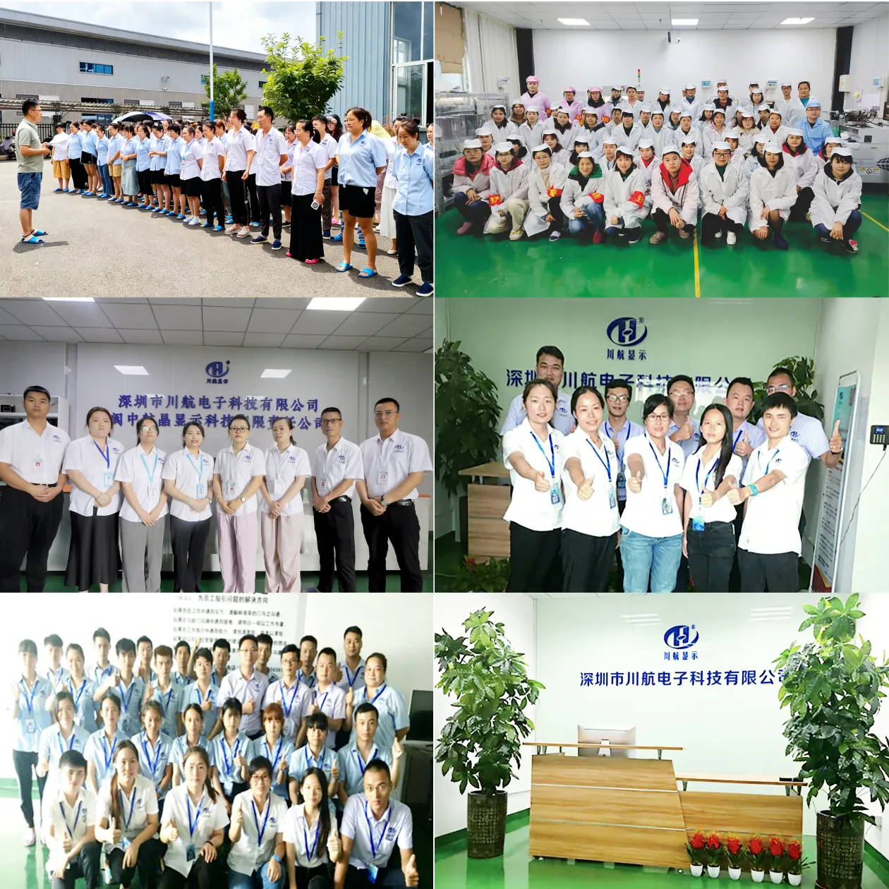
When scaling production, standardizing your component supply chain is a fundamental priority. Working with a specialized factory like Chuanhang Display ensures strict quality control from the initial ITO glass cutting to the final pin assembly. A dedicated manufacturer can provide precise optical testing, ensuring consistency in LED wavelengths or LCD contrast ratios across multiple production batches. This minimizes yield loss on your surface-mount technology (SMT) lines and keeps overall manufacturing costs predictable.
While high-resolution TFT and OLED screens dominate the smartphone and tablet markets, the demand for simplified numeric panels continues to grow in the B2B sector. The future of the seven segment display lies in enhanced integration and ultra-low power consumption.
We are seeing a heavy shift toward Chip-On-Glass (COG) technology, where the driving IC is bonded directly onto the ITO substrate. This allows a panel with dozens of segments to interface with a host microcontroller using just two or three wires (via I2C or SPI protocols), drastically simplifying PCB routing and reducing board space. Additionally, advancements in Vertical Alignment materials are bringing OLED-like contrast ratios to traditional numeric modules at a fraction of the cost.
Q1: What is the main difference between static and multiplexed driving in LCD panels?
A1: Static driving allocates one dedicated connection per segment, running at a 100% duty cycle for maximum contrast but requiring a high pin count. Multiplexed driving groups segments into a matrix of COM and SEG lines, drastically reducing the number of pins required but requiring precise AC voltage calculations to prevent ghosting.
Q2: How do I choose between transmissive and reflective polarizers?
A2: Choose reflective polarizers for battery-powered devices used in well-lit environments, as they consume almost zero power. Choose transmissive polarizers for environments that are consistently dark, requiring a dedicated LED backlight. Transflective is the hybrid choice for variable lighting conditions.
Q3: Can a seven segment display show alphabetical characters?
A3: Yes, but it is limited. It can comfortably display hexadecimal characters (A, b, C, d, E, F) and a few other letters (H, L, P, U, y). If your application requires rendering the full alphabet clearly, you should upgrade to a 14-segment or 16-segment alphanumeric module, or a dot-matrix panel.
Q4: What are the typical operating temperature ranges for industrial numeric panels?
A4: Commercial grade panels typically operate between 0°C to +50°C. Industrial-grade panels utilize specialized fluid and polarizers to achieve a standard wide range of -20°C to +70°C, with ultra-wide temperature versions capable of -40°C to +85°C (or even +105°C for automotive requirements).
Q5: How do elastomeric (Zebra) strips compare to metal pins for PCB integration?
A5: Zebra strips consist of alternating conductive and insulating silicone layers. They are highly cost-effective and handle shock well, but they require a mechanical housing/bezel to compress the strip between the panel and the PCB. Metal pins allow for simple, direct soldering (through-hole) without needing a compression bezel, though they add a slight premium to the component cost.
Navigating the specifications of optoelectronic hardware requires a deep understanding of electrical driving methods, substrate materials, and environmental constraints. By carefully selecting the right liquid crystal fluids, polarizers, and connection architectures, engineers can ensure their human-machine interfaces remain durable, readable, and highly cost-effective for mass production.
For hardware engineering teams and procurement officers seeking reliable component manufacturing, Chuanhang Display offers extensive expertise in both standard modules and fully customized tooling solutions tailored to your specific project requirements.
If you are currently drafting a BOM for a new project, require engineering support for your next seven segment display integration, or want to reduce costs on an existing product line, our technical sales team is ready to assist.