Alphanumeric and graphic monochrome liquid crystal displays remain a cornerstone of industrial control systems, medical instrumentation, and utility metering. Their persistence in the market, despite the rise of high-resolution color screens, is driven by low power consumption, high readability under direct sunlight, and simplified interface requirements. Among the historical standards in this sector, JHD display modules have long served as a reference point for hardware engineers designing legacy and modern micro-controller-based systems.
Integrating or sourcing these displays requires a thorough understanding of their physical architecture, liquid crystal chemistry, controller compatibility, and electrical characteristics. This guide provides an in-depth analysis of these technical parameters to assist procurement officers and design engineers in making informed sourcing decisions.
When selecting a monochrome LCD, the physical assembly method directly dictates the module's mechanical durability, profile thickness, and cost. Alphanumeric displays typically fall into two categories:
COB modules feature the driver integrated circuit (IC) mounted directly onto the printed circuit board (PCB) of the display assembly, protected by an epoxy resin "globe top."
Mechanical Stability: The PCB provides excellent structural support, making COB modules highly resistant to mechanical shock and vibration.Ease of Mounting: Integrated mounting holes in the PCB allow for straightforward mechanical fastening to housing bezels.Thickness: The presence of the PCB and epoxy dome results in a thicker profile (often between 8mm to 14mm, including the LED backlight).
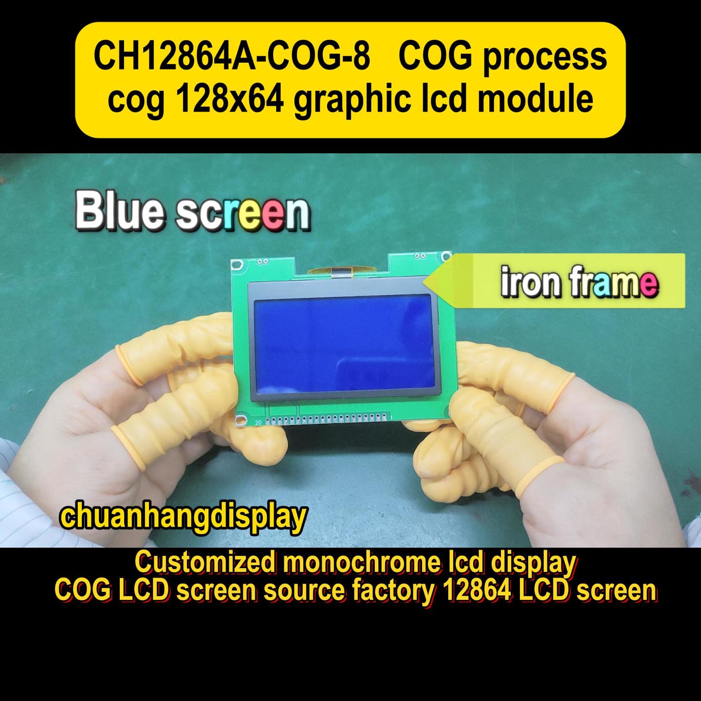
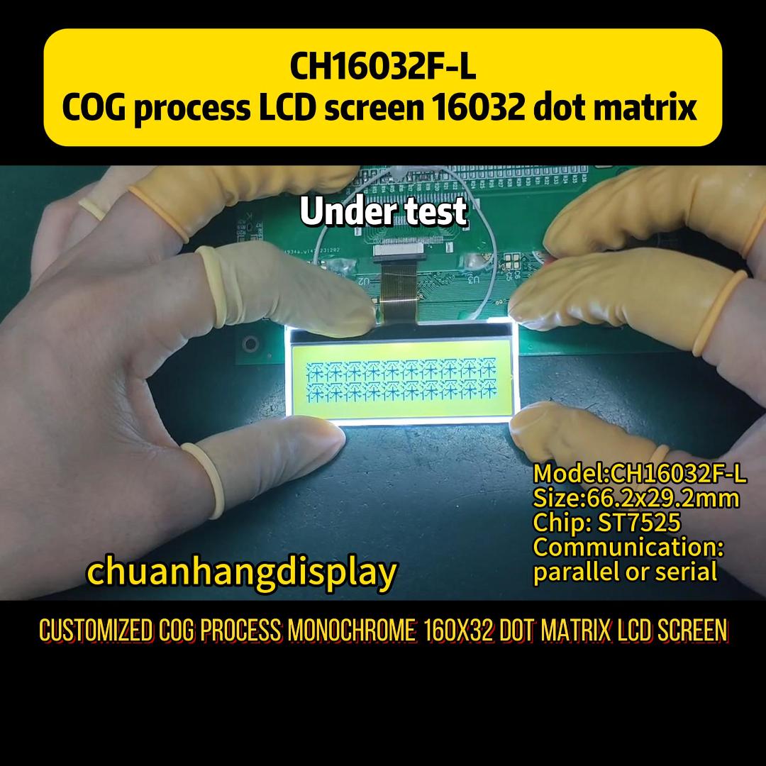
In COG configurations, the controller IC is mounted directly onto the glass substrate of the LCD panel.
Compact Footprint: COG displays eliminate the bulky PCB behind the glass, significantly reducing the overall module thickness (often under 3mm).Cost Efficiency: Fewer interconnects and the absence of an auxiliary PCB reduce material costs at high manufacturing volumes.Interconnection: Connection to the host controller is typically achieved via a Flexible Printed Circuit (FPC) tail, requiring precise hot-bar soldering or Z-axis conductive adhesive connectors on the main board.
The choice of liquid crystal fluid and polarizer type determines the display’s operating temperature range, viewing angle, and legibility under varying lighting conditions.
+-----------------------------------------------------------------+
| Fluid Type | Twist Angle | Contrast Ratio | Temperature Range |
+------------+-------------+----------------+---------------------+
| TN | 90° | Low-Medium | 0°C to +50°C |
| STN | 180° to 270°| Medium-High | -20°C to +70°C |
| FSTN | 180° to 270°| High (B&W) | -20°C to +70°C |
+-----------------------------------------------------------------+
Twisted Nematic (TN): The most cost-effective option, limited to low multiplexing rates (typically up to 1/16 duty cycle). TN displays offer a narrower viewing angle and are suited for basic consumer appliances operated within indoor environments.Super-Twisted Nematic (STN): Utilizing a higher molecular twist angle, STN displays provide a sharper electro-optical response curve. This allows for higher multiplexing rates (up to 1/240 duty or more), wider viewing angles, and improved contrast. They are available in Yellow-Green, Gray, and Blue modes.Film-Compensated STN (FSTN): By adding a polymer compensation film to the STN structure, the inherent coloration of the display is neutralized, resulting in a true black-on-white or white-on-black image. FSTN provides the highest contrast and widest viewing angles among standard passive-matrix displays, making it ideal for outdoor industrial terminals.
Reflective: Utilizes a rear polarizer that reflects ambient light. These modules require no power for a backlight, making them exceptionally low-power, though they are unreadable in dark environments.Transmissive: Requires a continuous backlight to be visible. The rear polarizer is transparent, allowing maximum light passage from the LED backlight, making it ideal for low-light or indoor applications.Transflective: A hybrid polarizer that reflects ambient light while allowing backlight transmission. This configuration ensures readability in both direct sunlight (reflective mode) and complete darkness (transmissive mode).
A primary reason for the widespread adoption of JHD display modules is their reliance on standardized control architectures. Most character displays are compatible with the industry-standard Hitachi HD44780 protocol or modern equivalent driver ICs, such as the Sitronix ST7066U or the AiP31066.
A standard JHD character module (such as the 16x2 configuration) employs a 16-pin interface, typically arranged in a single row or a 2x8 dual-row header:
VSS: Ground (0V)VDD: Power Supply (+5.0V or +3.3V)V0: Contrast Adjustment (typically adjusted via a 10k-ohm potentiometer connected between VDD and VSS)RS (Register Select): High for Data Register; Low for Instruction RegisterR/W (Read/Write): High for Read; Low for WriteE (Enable): Read/Write initiation signal (active high, falling-edge triggered)DB0 to DB7: Parallel Data Bus lines (8-bit bidirectional data lines)LED+ (A): Backlight Anode (requires a current-limiting resistor)LED- (K): Backlight Cathode
8-Bit Parallel Interface: Uses all eight data lines (DB0–DB7) for fast data throughput. Best suited for high-speed systems where GPIO pin count on the host processor is not a constraint.4-Bit Parallel Interface: Sends data in two consecutive 4-bit nibbles using only DB4–DB7. This reduces the required I/O pin count on the microcontroller from eleven to seven, which is highly beneficial for cost-sensitive designs.I2C / SPI Serial Bridges: For modern microcontrollers with restricted pin budgets, serial adapter boards using PCF8574 I/O expanders are frequently mounted to the back of the JHD panel, reducing the physical connection to just four wires (VCC, GND, SDA, SCL).
Industrial hardware designers face several operational challenges when deploying monochrome LCD displays. Addressing these variables during the initial selection phase prevents premature field failures and system redesigns.
As ambient temperature decreases, the viscosity of the liquid crystal fluid increases, slowing down response times and altering the threshold voltage. This shift causes the display text to fade or become completely saturated black.To mitigate this, industrial-grade systems must incorporate active temperature compensation circuits. Some high-end display modules include an integrated temperature sensor that dynamically adjusts the V0 contrast voltage. For standard modules, an external thermistor circuit can be designed to regulate the V0 bias relative to ambient temperature changes.
Industrial environments are prone to electrical noise from motors, relays, and switching power supplies. Standard displays with unshielded bezels can experience character corruption or latch-up when exposed to ESD.Implementing proper shielding is vital. The metal bezel (frame) of the LCD must be securely grounded to the system chassis ground. Additionally, bypass capacitors (0.1µF and 10µF) should be placed as close as possible to the VDD and VSS pins of the display to filter out high-frequency power supply noise.
A significant challenge in the industrial sector is the obsolescence of display components. Consumer-grade displays often have a lifecycle of less than two years. When sourcing components, it is crucial to partner with manufacturers that guarantee form-fit-function compatibility for a minimum of five to ten years.
Sourcing monochrome LCD modules involves balancing component cost, tooling expenses, and production lead times. While generic standard modules are highly commoditized, specific industrial requirements often necessitate customized solutions.
Tooling Fees (NRE): For custom segment layouts, glass sizing, or custom FPC routing, manufacturers charge a Non-Recurring Engineering (NRE) fee. While segment LCD tooling is relatively inexpensive (typically $1,500 to $3,000 USD), graphic dot-matrix or custom COG tooling can be higher.Backlight Lifetime: Standard commercial backlights may only have a half-brightness lifetime of 20,000 hours. For industrial operations running continuously (24/7), sourcing backlights rated for 50,000 hours or more prevents premature dimming.Minimum Order Quantities (MOQs): Standard catalog displays can often be purchased in small batches. However, custom modifications (such as custom polarizers, wide temperature fluid, or customized cable assemblies) usually carry MOQs ranging from 1,000 to 5,000 units per production run.
To manage these sourcing complexities, working with established, quality-focused manufacturers is advantageous. This is where specialized partners like Chuanhang Display step in. By offering comprehensive quality control, customized tail connections, and alternative component options, Chuanhang Display helps industrial buyers maintain steady supply chains, especially when looking for compatible replacements for discontinued JHD parts.
+-----------------------------------------------------------------------------+
| Layout | Character/Dot Matrix | Typical Controller | Main Applications |
+--------+----------------------+--------------------+------------------------+
| 16x2 | 16 Characters x 2 L | ST7066U / HD44780 | UPS, Meters, Printers |
| 20x4 | 20 Characters x 4 L | ST7066U / AIP31066 | Industrial controllers |
| 128x64 | 128 x 64 Dots | ST7567 / UC1609C | Medical devices, Handhelds|
| 240x64 | 240 x 64 Dots | T6963C / RA6963 | CNC Machines, Marine |
+-----------------------------------------------------------------------------+
A1: Standard modules typically operate at either +5.0V or +3.3V DC. It is vital to verify the specific driver IC specification, as supplying 5V to a 3.3V rated controller can cause permanent damage, while supplying 3.3V to a 5V controller will result in poor contrast or a blank screen.
A2: The contrast is controlled by the analog voltage applied to the V0 pin (Pin 3). By adjusting the voltage between VSS (0V) and VDD, you can modify the alignment of the liquid crystal molecules. For most 5V modules, the optimal contrast voltage is around 0.5V to 4.5V relative to VDD, which is typically set using a 10k-ohm variable resistor.
A3: While OLEDs offer superior contrast and viewing angles, direct hardware replacement can be challenging. OLEDs have different power profiles, draw higher peak currents during bright screen states, and are susceptible to image burn-in in static industrial interfaces. Additionally, ensure the controller register mapping is fully compatible before changing display technologies.
A4: Yellow-green backlights generally use GaAsP or GaP LED chips, which are highly efficient and offer long life spans at lower costs, but they require a higher driving current. White LED backlights utilize blue LED chips with a yellow phosphor coating; they provide a more modern aesthetic and high contrast when paired with FSTN glass, but their half-life brightness can degrade faster under high-temperature conditions.
A5: Most initialization failures stem from improper timing sequences in the host controller firmware. Upon power-up, the display controller requires a specific wait time (typically at least 15ms to 40ms after VDD reaches 4.5V) before any initialization commands are sent. If the microcontroller boots faster than the LCD controller, the initialization sequence will fail, leaving the display blank or showing a single row of solid blocks.
Selecting the correct display technology is a balance of electrical compatibility, mechanical constraints, and long-term component availability. Whether you require standard configurations or customized display panels, Chuanhang Display provides the engineering expertise and manufacturing consistency needed to secure your production lifecycle.
Contact Chuanhang Display today to discuss your project requirements, request detailed technical datasheets, or obtain a quote for your customized display production runs. Our engineering team is ready to assist you with form-fit-function replacements and new design integrations.