In industrial display engineering, selecting the appropriate display packaging technology is a primary factor in determining product lifespan, power efficiency, and physical dimensions. Among the various methods of integrating driver electronics with liquid crystal panels, Chip-on-Glass technology has become a standard approach for compact, high-reliability designs. Selecting the appropriate cog module is a primary decision for hardware engineers designing equipment for industrial, automotive, and medical fields where space is limited and mechanical durability is necessary.
This technical guide provides an objective analysis of Chip-on-Glass display systems, focusing on material composition, assembly physics, common industry pain points, and procurement strategies for B2B buyers.
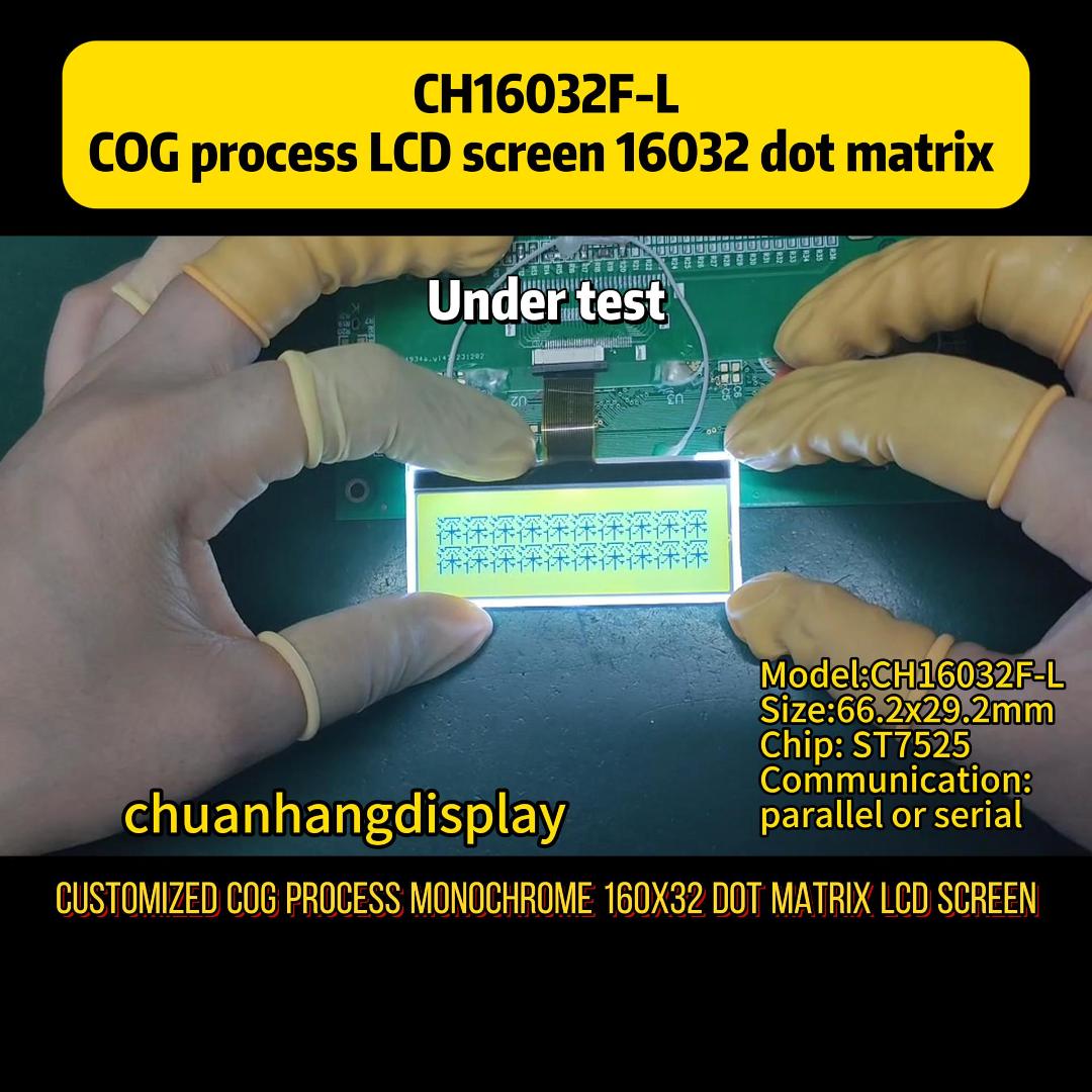
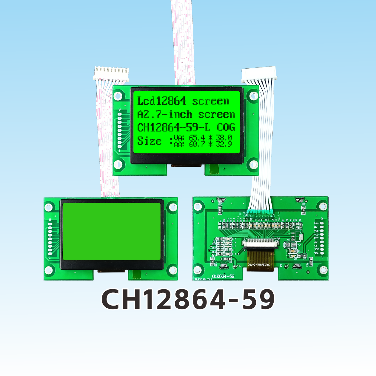
The fundamental concept of Chip-on-Glass (COG) packaging involves the direct mounting of the bare integrated circuit (IC) driver chip onto the glass substrate of the LCD panel. This eliminates the need for an intermediate flexible printed circuit (FPC) or a separate printed circuit board (PCB) for the driver chip, drastically reducing the overall thickness and complexity of the display system.
In a standard cog module, the interconnection between the silicon driver IC and the conductive traces on the glass substrate is achieved using Anisotropic Conductive Film (ACF). The glass substrate is patterned with Indium Tin Oxide (ITO) electrodes, which serve as highly transparent, conductive pathways linking the driver IC to the active display pixels and the input FPC.
The electrical connection is established through a thermo-compression bonding process. The process relies on three primary elements:
Because the driver IC is placed directly on the glass surface, the physical footprint of a cog module remains exceptionally compact, which minimizes parasitic capacitance and enhances signal integrity over high-resolution matrices.
The reliability of a display module is tied to the physical properties of its constituent materials. In industrial environments, mismatching thermal expansion coefficients or choosing sub-standard glass substrates can lead to premature field failures.
Most industrial displays utilize either Soda-Lime glass or Borosilicate glass. Borosilicate glass is preferred for high-reliability applications due to its lower coefficient of thermal expansion (CTE), which minimizes stress on the micro-fine ITO traces during thermal cycling. Substrate thickness typically ranges from 0.4 mm to 0.7 mm, balancing structural rigidity with weight constraints.
The adhesive layer must withstand mechanical vibrations and moisture ingress. Epoxy-based ACFs are standard for high-durability displays because they offer superior chemical resistance and high adhesion strength compared to acrylic-based alternatives. The density of the conductive particles within the film must be precisely controlled: too low a density leads to open circuits, while excessive density increases the risk of adjacent short circuits (fine-pitch shorting).
The contact pads on the driver IC are typically bumped with gold (Au) to prevent oxidation and ensure low contact resistance. The height uniformity of these gold bumps must be controlled within sub-micron tolerances (usually ±0.5 μm) to guarantee uniform pressure across all contact points during the bonding cycle.
To understand why hardware designers choose a cog module, it is useful to compare it with alternative packaging methodologies: Chip-on-Board (COB) and Chip-on-Film (COF).
| Parameter | Chip-on-Board (COB) | Chip-on-Film (COF) | Chip-on-Glass (COG) |
|---|---|---|---|
| IC Placement | Mounted on external PCB | Mounted on flexible circuit (FPC) | Mounted directly on display glass |
| Module Thickness | Thickest (typically > 5.0 mm) | Thin (typically < 2.0 mm) | Thinnest (typically < 1.5 mm) |
| Minimum Pitch Size | High (> 100 μm) | Medium (~ 30 to 50 μm) | Ultra-fine (< 20 μm) |
| Vibration Resistance | Moderate | High (flexible) | Very High (solid state) |
| Tooling Cost | Low | High | Moderate to High |
COB is economical for low-resolution character displays with ample housing depth. COF offers flexibility, making it suitable for curved screens or bezel-less designs, but it carries higher material and processing costs. A cog module provides the optimum balance for high-density, low-profile industrial designs, delivering high vibration resistance and fine-pitch compatibility at a scalable production cost.
While Chip-on-Glass technology is highly mature, system integration and harsh operational environments can expose specific technical vulnerabilities. As an established LCD manufacturer, Chuanhang Display integrates strict quality controls to mitigate these risks at the design phase.
The Challenge: Silicon, glass, and copper-plated FPCs expand and contract at different rates under thermal stress. In outdoor or automotive applications experiencing temperatures from -40°C to +85°C, this thermal stress can cause delamination at the ACF interface, resulting in pixel line defects or total display failure.
The Mitigation: Utilizing low-CTE glass substrates combined with high-Tg (Glass Transition Temperature) epoxy ACFs helps maintain bond integrity. Specialized stress-relief cuts in the outer bezel casing can also prevent external mechanical forces from transferring to the glass edge.
The Challenge: Humidity can penetrate the micro-gaps at the edge of the glass panel. If moisture reaches the ITO traces while voltage is applied, electrochemical migration can occur, leading to trace corrosion and permanent open circuits.
The Mitigation: Display assemblies must utilize high-performance edge-seal silicone coatings or UV-curable acrylic resin barriers over the exposed ITO traces. Working with manufacturers like Chuanhang Display ensures that secondary environmental barrier coatings are applied uniformly under automated dispensing systems.
The Challenge: Because the driver IC is situated directly on the glass, any electrostatic discharge applied to the bezel or glass cover can easily propagate through the ITO traces directly to the silicon die, causing latent damage or immediate dielectric breakdown.
The Mitigation: Integrating transient voltage suppressors (TVS) on the input FPC, along with proper grounding of the metal bezel and anti-static coatings on the polarizer, provides a low-impedance path to ground, bypassing the sensitive driver IC.
When evaluating a cog module for mass production, purchasing managers and hardware engineers must look beyond the initial unit price to calculate the total cost of ownership. Several structural factors influence the pricing and supply chain stability of these components.
The total cost of a display is heavily dependent on the driver IC. In the semiconductor market, display drivers can go end-of-life (EOL) with short notice. Sourcing from a partner who maintains strong relationships with wafer foundries is vital. Partnering with an experienced vendor such as Chuanhang Display ensures that long-term supply agreements and pin-compatible IC alternatives are planned well in advance, avoiding costly PCB redesigns.
While standard catalog displays are readily available, specialized industrial applications often require customized active areas, unique FPC routing, or high-brightness backlights. Customizing a display involves several non-recurring engineering (NRE) costs:
Buyers should confirm that their supplier uses automated optical inspection (AOI) and comprehensive electrical testing at each stage of customization to ensure high yields and minimize long-term warranty claims.
Q1: What is the typical operating temperature range of an industrial-grade cog module?
A1: Industrial-grade modules typically operate from -20°C to +70°C, while automotive-grade modules extend this range from -40°C to +85°C. Performance at extreme low temperatures is governed by the liquid crystal fluid's response time, while high-temperature limits are bound by the clear point of the liquid crystals and the glass transition temperature of the ACF adhesive.
Q2: Can a damaged driver IC on a Chip-on-Glass module be repaired or reworked?
A2: Generally, reworking a bonded driver IC at the system integration stage is not economically viable. The ACF bonding process is semi-permanent; removing a bonded IC requires thermal heating that can degrade the adjacent ITO coatings and glass substrate. Rework is typically confined to the manufacturing facility before final module assembly.
Q3: How does Chip-on-Glass technology affect the power consumption of the display?
A3: By eliminating long copper wire runs and intermediate PCBs, COG minimizes parasitic resistance and capacitance along the signal lines. This allows the driver IC to operate with lower drive voltages and reduced power consumption, making it highly advantageous for battery-operated handheld devices.
Q4: Why does a COG display sometimes require an external bezel or frame?
A4: Although the glass substrate provides the display surface, the bare silicon driver IC on the edge of the glass is physically exposed. A metallic or plastic bezel is used to protect this fragile silicon edge from mechanical impact, distribute mounting stress, and provide a path for grounding ESD charges.
Q5: What are the primary factors that determine the NRE tooling cost for a custom COG display?
A5: The primary cost drivers for NRE include the complexity of the ITO photolithography masks, the size of the glass substrate, custom FPC design layers, and custom injection-molded plastic frames for the backlight. Standardizing the outer glass dimension while customizing only the FPC layout is a common method used to keep tooling costs manageable.
Selecting the optimal display packaging requires balancing mechanical constraints, environmental factors, and unit economics. For custom integrations, high-reliability requirements, or detailed volume quotations, contact our engineering department to discuss your specific application needs.