In modern industrial and commercial equipment design, selecting an appropriate human-machine interface (HMI) requires balancing readability, reliability, power consumption, and cost. While high-resolution color thin-film transistor (TFT) displays and organic light-emitting diode (OLED) screens dominate consumer devices, the standard character-based or dot matrix lcd display module continues to occupy a highly important position in professional, industrial, and medical equipment. These modules offer unmatched longevity, low power requirements, and exceptional readability under direct sunlight when configured correctly.
For system integrators and hardware engineers, understanding the subtle differences in drive methodologies, physical packaging, and optical configurations is necessary to avoid system failures in the field. This article provides a technical analysis of liquid crystal displays utilizing dot matrix configurations, offering detailed insights into physical construction, electrical interfaces, optical modes, and supplier selection parameters.
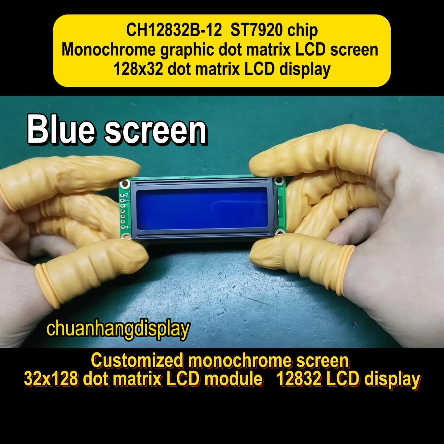
An monochrome liquid crystal display functions by using nematic liquid crystal molecules that rotate when an electric field is applied, thereby controlling the passage of polarized light. In a dot matrix configuration, these liquid crystals are organized into a grid of individual pixels (dots), which are individually or multiplexed-driven to form alphanumeric characters, symbols, or custom graphical elements.
To understand the reliability of a dot matrix lcd display module, it is helpful to examine its structural layers. Typically, the module consists of several stacked components:
One of the initial decisions when selecting a display module is the packaging style of the driver integrated circuit (IC).
Chip-on-Board (COB): In a COB configuration, the driver IC is mounted directly onto the system PCB and protected by a drop of black epoxy resin (commonly referred to as a "globe top"). The LCD glass panel is connected to the PCB via elastomeric connectors or pins. COB displays are physically robust, easy to mount mechanically using integrated screw holes, and highly suitable for environments subject to high vibration.
Chip-on-Glass (COG): In a COG configuration, the driver IC is bonded directly onto the extended lip of the display's glass substrate using anisotropic conductive film (ACF). This eliminates the need for a separate PCB substrate for the IC, resulting in a significantly thinner, lighter, and more cost-effective module. COG displays are ideal for handheld, battery-powered devices where space is at a premium, though they require more careful mechanical design to protect the glass edges from impact.
Choosing the correct liquid crystal fluid for a dot matrix lcd display module dictates its thermal limits, contrast ratio, and visual performance. There are three primary material technologies employed in industrial applications:
TN displays feature liquid crystal molecules that twist by 90 degrees between the two glass substrates. They are highly economical and offer fast response times. However, TN panels have limited viewing angles and lower contrast ratios when multiplexed, making them best suited for simple, direct-drive segment displays or low-duty character displays (such as 8x1 or 16x1 characters).
STN technology increases the liquid crystal molecules' twist angle to between 180 and 270 degrees. This higher twist angle steepens the electro-optical transfer curve, allowing for much higher multiplexing rates (up to 1/240 duty cycle). This enables dense dot matrices (such as 128x64 or 240x128 pixels) to maintain acceptable contrast and viewing angles. STN displays typically exhibit a yellow-green background with dark blue/black pixels, or a blue background with white pixels.
FSTN adds an optical compensation film to the outer surface of an STN display. This film neutralizes the inherent yellow-green or blue coloration of the STN fluid, resulting in a high-contrast black-and-white display. FSTN modules provide the best readability, widest viewing angles, and sharpest contrast among passive-matrix monochrome displays, though they carry a higher manufacturing cost.
When drafting a component specification sheet for sourcing, engineers must carefully outline the electrical and optical limits to ensure system stability. Below are the key engineering metrics that must be defined:
| Parameter | Standard Range | Industrial Wide Temp Range | Pivotal Design Impact |
|---|---|---|---|
| Operating Voltage (VDD) | 5.0V ± 10% | 3.3V ± 10% / 2.7V - 5.5V | Determines compatibility with modern low-power microcontrollers without level-shifting. |
| Operating Temperature | 0°C to +50°C | -20°C to +70°C (or -30°C to +85°C) | Viscosity of liquid crystal increases at low temperatures, causing slow response times. |
| Duty Cycle | 1/16 duty (typical) | Up to 1/128 or 1/240 duty | Refers to the fraction of the frame time that each row is addressed. Higher duty ratios require higher voltage stability. |
| Bias Ratio | 1/4 or 1/5 bias | 1/7 to 1/9 bias | The voltage division ratio used to drive the display. Proper bias matching prevents ghosting. |
| Response Time (Tr + Tf) | 200ms to 300ms | Varies dynamically with temperature | Dictates the maximum refresh rate and readability of moving menus or parameters. |
How the display interacts with ambient light and backlighting determines its suitability for different operating environments:
Monochrome dot matrix modules are specified where high-resolution color is unnecessary, but continuous uptime, mechanical toughness, and cost efficiency are required. Key sectors include:
Programmable Logic Controllers (PLCs), motor drives, and environmental control panels rely on these displays to show numerical values, operating states, and fault codes. These environments are often harsh, subject to high temperatures, dust, and electrical noise from switching relays and motors.
Devices such as fluid pumps, blood pressure monitors, and laboratory centrifuges utilize dot matrix modules for their clear contrast and predictable behavior. Unlike complex modern operating systems driving TFT screens, monochrome displays driven by basic microcontrollers have virtually zero risk of software crashes or lag, which is highly important for patient safety equipment.
When integrating these displays, design engineers frequently encounter specific challenges that must be designed around during the early stages of product development:
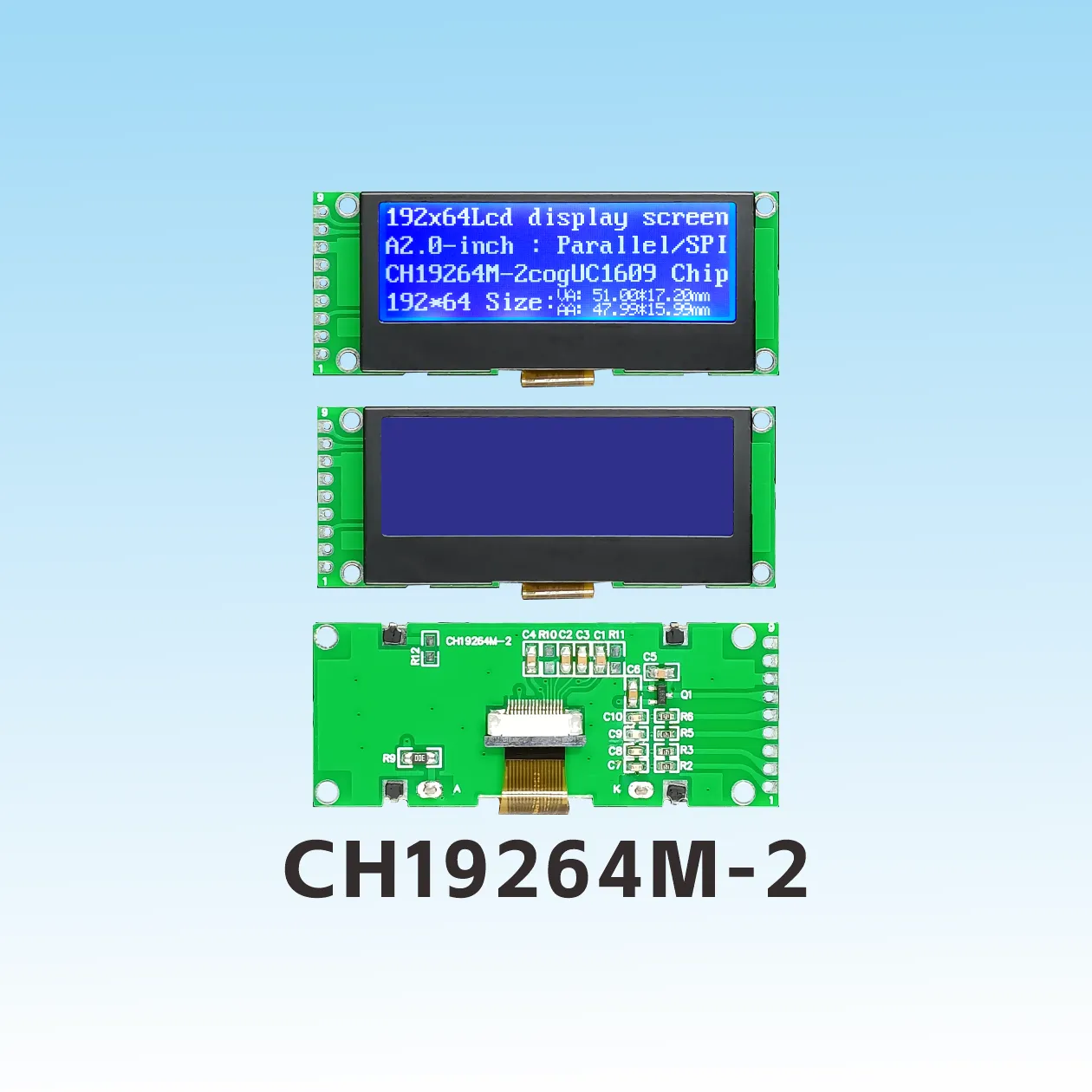
When selecting a supplier for a display module, hardware procurement teams must look past the initial unit price. The total cost of ownership is heavily influenced by quality control, longevity of supply, and technical support.
To successfully evaluate a supplier, consider the following points:
Q1: What are the main differences between a character LCD and a dot matrix lcd display module?
A1: A character LCD is pre-patterned to display specific blocks of character fonts (typically a 5x8 pixel grid for each character) with fixed gaps between the character blocks. It cannot easily display custom graphics or connected lines across the entire display. A true dot matrix display features a continuous, uninterrupted grid of pixels (such as 128x64 or 240x128), allowing the software to render both text of any size/font and custom graphics, charts, or icons anywhere on the panel.
Q2: Can I drive a 5V dot matrix display using a 3.3V microcontroller?
A2: Direct connection can result in very weak contrast or no display at all, as the liquid crystal requires a specific threshold voltage to align correctly. To drive a 5V display with a 3.3V controller, you either need a level shifter for the data lines and an external negative voltage generator for the LCD drive voltage (V0), or you must choose a display module designed with a built-in voltage booster that operates directly on a 3.3V power supply.
Q3: What is the purpose of the V0 pin on the display interface?
A3: The V0 pin (sometimes labeled Vee) is used to adjust the operating voltage applied to the liquid crystal fluid, which directly controls the display contrast. By placing a variable resistor (typically 10k or 20k Ohms) between VDD and VSS (ground) and routing the wiper to V0, engineers can manually adjust the screen's contrast to compensate for environmental temperature variations and component tolerances.
Q4: How does temperature affect a dot matrix lcd display module?
A4: Temperature affects the physical properties of the liquid crystal fluid. As temperatures drop toward sub-zero levels, the liquid crystal becomes highly viscous, which dramatically slows down response times (causing characters to smudge or ghost during transitions). At extremely high temperatures, the fluid can transition from its liquid crystal phase to an isotropic liquid phase, causing the display to lose all contrast and turn black. Specifying wide-temperature fluid ranges prevents these failures.
Q5: What is the typical lifespan of an LED backlight in these display modules?
A5: Modern LED backlights used in industrial monochrome modules typically have a lifespan of 50,000 to 100,000 hours of continuous operation before the brightness drops to 50% of its original value. To maximize this lifespan, designers should avoid running the backlight LEDs at their absolute maximum current rating and implement software-controlled sleep modes to turn off the backlight during periods of user inactivity.
For industrial system designers, finding the ideal configuration requires a balanced understanding of physical packaging, drive parameters, and ambient lighting conditions. Sourcing a customized display is a long-term technical partnership that demands rigorous quality verification and reliable supply chains.
If you are currently designing an industrial instrument, medical device, or control interface, contact Chuanhang Display today to discuss your project requirements, receive detailed technical data sheets, or request sample modules for engineering evaluation. Our engineering team is ready to assist you in selecting the optimal configuration for your specific environmental and electrical constraints.