For decades, character liquid crystal displays have been the standard interface for industrial machinery, server racks, and prototyping equipment. While graphical screens get the attention in consumer tech, the reliable 20x4 lcd display remains a critical component for systems that require clear, alphanumeric data readout without the processing overhead of a full matrix panel.
The jump from a standard 16x2 screen to a 20x4 format offers double the data capacity. This allows engineers to display four full lines of text with twenty characters per line. It changes the user interface from a scrolling frustration into a comprehensive dashboard. At Chuanhang Display, we continue to see high volume demand for this form factor because of its balance between size, readability, and ease of programming.
This article covers the engineering nuances, interface options, and sourcing considerations for this enduring display technology.
The core appeal of this module is its standardization. Almost every 20x4 lcd display on the market utilizes a controller compatible with the Hitachi HD44780 standard. This universality means code written for one manufacturer’s screen will likely work on another’s with minimal changes.
The screen consists of a liquid crystal layer sandwiched between two glass plates. The display is divided into a grid of 80 separate character blocks. Each block typically contains a 5x8 pixel matrix. This matrix is where the liquid crystal twists to block light, forming letters, numbers, or custom symbols.
Unlike a graphic LCD where you address individual pixels, here you address character slots. This drastically reduces the burden on your main microcontroller. You simply send the ASCII code for the letter 'A', and the onboard controller handles the pixel rendering. This efficiency is why these screens are still found in high-end medical pumps and network switches.
Connecting a 20x4 lcd display to a system board usually involves one of three methods. The choice depends on available I/O pins and the electrical noise environment.
Parallel Interface (8-Bit and 4-Bit)The native interface of the LCD controller is parallel. In 8-bit mode, you use 8 data pins (D0-D7) plus control pins (RS, RW, E). This is the fastest method but consumes a massive amount of board space.
Engineers often opt for 4-bit mode. This sends the byte in two chunks (nibbles) over four data pins (D4-D7). It saves four pins on the microcontroller with a negligible speed penalty for human-readable text. This is the standard wiring method for direct PCB integration in industrial controllers.
I2C IntegrationFor rapid prototyping or pin-constrained modern microcontrollers, the I2C interface is dominant. This usually involves a "backpack" board soldered to the back of the LCD module. It converts the parallel signals into a serial I2C stream, requiring only two data wires (SDA and SCL) plus power. While slightly slower, it simplifies wiring harnesses significantly.
Not all screens look the same. The visual performance of a 20x4 lcd display is defined by its fluid type and polarizer arrangement.
Yellow-Green STNThis is the classic industrial look. It features a yellow-green background with dark grey or black pixels. It is incredibly robust and easy to read under bright office lighting. It usually employs a transflective polarizer, meaning it is readable with or without the backlight.
Blue STN (Negative Mode)This variant features a deep blue background with white text. It is a "transmissive" display, meaning the backlight must be on for the text to be visible. This offers higher contrast in low-light environments and a more modern aesthetic for server rooms or audio equipment.
FSTN (Film Super Twisted Nematic)FSTN adds a compensation film to the glass stack. This results in a sharp black-and-white display. It offers the highest contrast ratio and wider viewing angles compared to standard STN. For outdoor equipment, FSTN is often the preferred upgrade path.
One technical quirk that often confuses new developers is the memory addressing of the 20x4 lcd display. The screen lines are not contiguous in the controller’s memory.
Internally, the controller often treats the screen as two lines of 40 characters, cut in half and stacked.
Line 1 starts at address 0x00.Line 2 starts at address 0x40.Line 3 actually continues from where Line 1 "ended" in memory (Address 0x14).Line 4 continues from Line 2 (Address 0x54).
If you write a long string of text without cursor management, the text will run from Line 1 directly to Line 3, skipping Line 2. Understanding this non-linear DDRAM (Display Data RAM) map is essential for writing clean firmware.
While the module comes with a built-in font table (usually English/Japanese or English/Cyrillic), it also includes RAM for custom characters (CGRAM).
You can define up to eight custom 5x8 pixel patterns. This is incredibly useful for industrial applications. You can create symbols for "Degrees Celsius," "Pump On," "Warning Bell," or even battery level bars.
At Chuanhang Display, we often advise clients on how to utilize these custom slots to create intuitive user interfaces. Instead of writing "Battery Low," a blinking empty battery icon created in CGRAM communicates the status instantly and saves screen space.
The physical footprint of these modules is fairly standardized, but tolerances matter. The typical module measures approximately 98mm by 60mm. However, the placement of mounting holes can vary slightly between manufacturers.
When designing a casing, you must account for the "View Area" versus the "Active Area." The metal bezel frame holds the glass and compresses the zebra strip connectors. You should never apply pressure to this metal frame during mounting, as it can warp the connection and cause segments to disappear.
Mounting standoffs should align with the PCB holes. Additionally, if the device will be used in a humid environment, the bezel needs to be grounded effectively to prevent static buildup from scrambling the display controller.
The liquid crystals themselves consume micro-amps of power. The backlight, however, is a different story. The LED array behind a 20x4 lcd display typically draws between 20mA and 60mA depending on brightness.
In battery-powered devices, you cannot leave the backlight running at 100%. Implementing a transistor or MOSFET on the backlight cathode allows the microcontroller to use PWM (Pulse Width Modulation) to dim the display.
We also recommend a current-limiting resistor if one is not built into the module. Some modules include a resistor (like R8 or R9 on the back PCB), but others expect the main board to limit the current. Connecting 5V directly to the backlight anode without checking this can burn out the LEDs instantly.
For commercial products, the long-term availability of the component is vital. Unlike TFT screens which change form factors every few years, the 20x4 lcd display has a stable supply chain.
However, variations exist in the quality of the LED backlight and the grade of the glass. Cheaper modules may use LEDs that fade in brightness after only a few thousand hours.
Chuanhang Display focuses on industrial-grade modules. This means we prioritize high-stability liquid fluids that don't freeze at -10°C and backlights rated for 50,000+ hours. When sourcing for a product that has a lifecycle of 5 to 10 years, ensuring your supplier doesn't change the controller chip or the pinout unexpectedly is crucial for manufacturing continuity.
Even experienced engineers run into issues during the first bring-up of a new board.
The "Black Blocks" on Line 1 and 3This is the most common error. If you power up the screen and see solid black squares on the first and third lines, but nothing on the others, it usually means the screen is initialized but has not received valid data commands. It can also indicate the contrast voltage (Vo pin) is too low (too close to ground).
Fading CharactersIf characters appear but fade away, the voltage supply might be sagging, or the contrast potentiometer is drifting. The Vo pin is sensitive; it sets the bias voltage for the liquid crystals. A stable voltage divider or a precision trimpot is required here.
Garbage CharactersRandom symbols usually indicate timing issues or electrical noise on the Enable (E) line. If the cables between the MCU and the screen are too long (over 20cm), they act as antennas. Reducing wire length or adding a small capacitor across power lines can resolve this.
The pricing of a 20x4 lcd display is influenced by three main factors:
Operating Temperature: Standard displays work from 0°C to 50°C. "Wide Temperature" variants work from -20°C to +70°C. The chemical fluid for wide temps is more expensive.Backlight Color: Standard yellow-green is the cheapest. Blue or RGB backlights add cost.Connector Type: Soldering headers manually adds labor cost. Ordering modules with pre-soldered headers or specific JST connectors from the factory increases unit price but lowers assembly time.
Despite the influx of touchscreens, the 20x4 lcd display retains its title as the most efficient way to display alphanumeric data in industrial settings. Its distinct four-line structure allows for a header, two lines of data, and a footer status line, creating a logical hierarchy of information.
Successful integration requires attention to the memory map, careful management of backlight current, and the selection of the right optical mode for the environment. By working with a dedicated partner like Chuanhang Display, manufacturers can ensure they are getting modules that meet the rigorous demands of field deployment, ensuring that the text remains crisp and readable for the life of the machine.
Q1: How do I adjust the contrast on a 20x4 LCD display?
A1: Contrast is controlled by the Vo pin (usually Pin 3). You need to apply a voltage between 0V (Ground) and 5V (VCC) to this pin. Typically, a 10k potentiometer is connected with one leg to 5V, one to GND, and the wiper to Vo. As you turn the wiper closer to Ground, the pixels get darker. If connected directly to 5V or left floating, the text will likely be invisible.
Q2: Can I use a 5V 20x4 LCD with a 3.3V microcontroller like an ESP32?
A2: It is possible but requires care. The logic signals from the 3.3V MCU might not be high enough to trigger the 5V LCD controller reliably, and the 5V return signals from the LCD could damage the MCU. The best practice is to use a Logic Level Shifter between the two. Alternatively, you can source a module specifically designed for 3.3V operation from Chuanhang Display, which has the correct charge pump built-in.
Q3: Why is my text appearing on the wrong lines?
A3: This is due to the non-linear memory mapping. Line 1 continues logically to Line 3, and Line 2 continues to Line 4. If you write a string longer than 20 characters, it will wrap to the third line, not the second. You must explicitly send a "Set Cursor" command to the controller to move the writing position to the start of the second line (usually address 0x40).
Q4: What is the lifespan of the backlight on these displays?
A4: The typical LED backlight on an industrial-grade module is rated for roughly 50,000 hours of continuous operation before it drops to half brightness. This lifespan can be significantly extended by driving the LEDs at 70-80% of their rated current or by implementing a screen-saver timeout in your firmware that turns the backlight off when inactive.
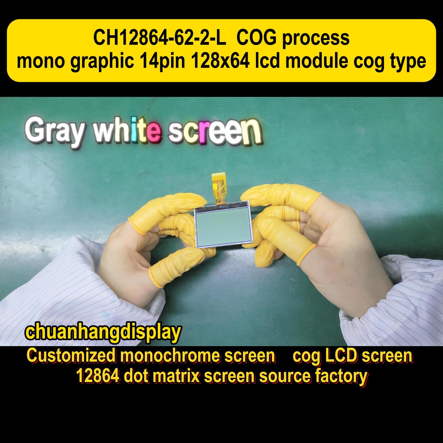
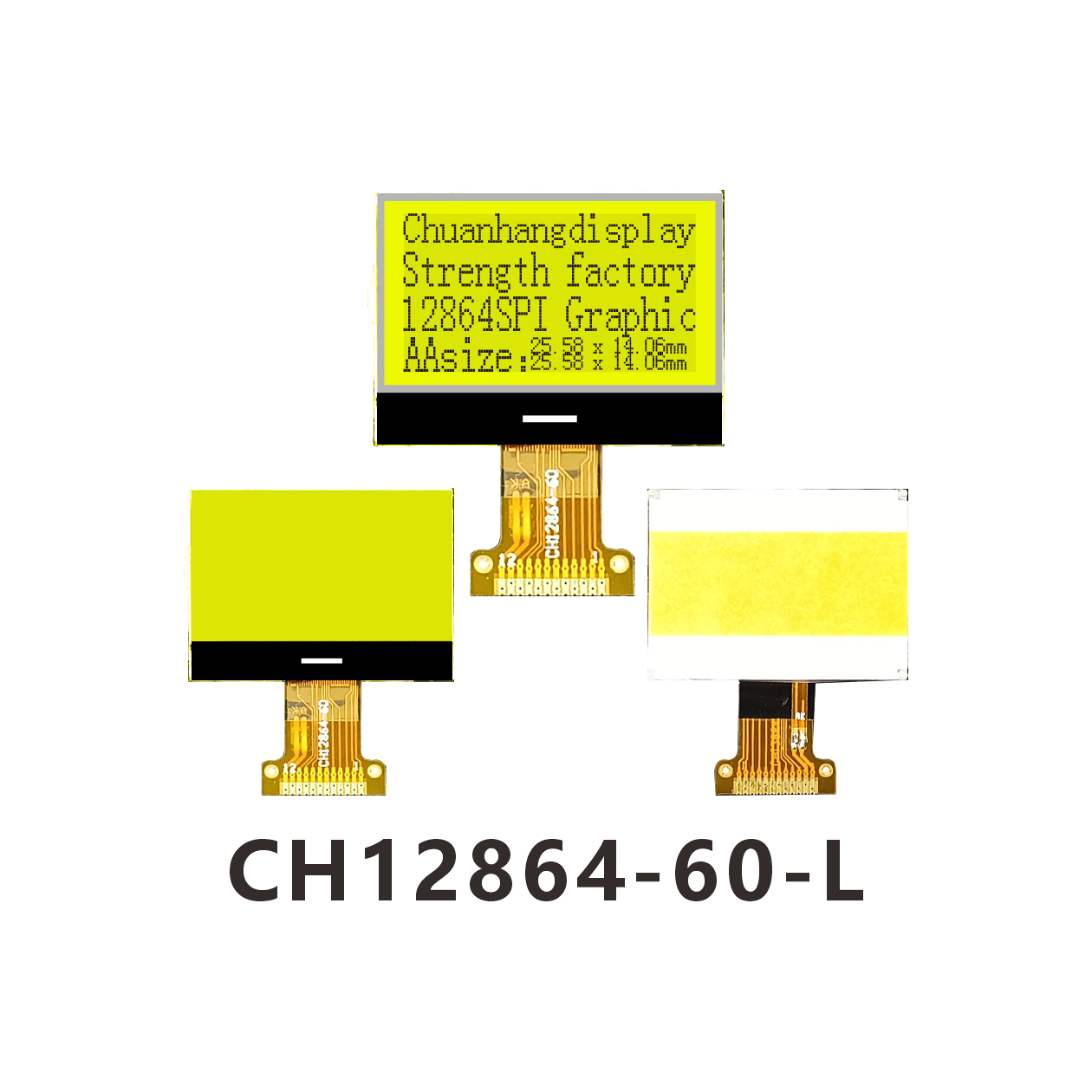
Q5: What is the difference between COB and COG construction in these displays?
A5: COB (Chip On Board) is the traditional method where the controller chip is encapsulated in a black blob of epoxy on the back PCB. It is bulky but extremely durable. COG (Chip On Glass) mounts the controller directly onto the glass edge. COG makes the 20x4 lcd display much thinner and lighter, but it can be more fragile mechanically and often requires a specialized bezel for mounting.