Designing modern portable electronics is an exercise in space optimization. Whether you build handheld medical monitors, smart utility meters, or battery-operated IoT sensors, you face constant pressure to shrink physical dimensions while boosting battery longevity.
Traditional display modules often present a mechanical bottleneck. Bulky printed circuit boards (PCBs) add unwanted millimeters to casing thickness, and complex wire interconnects introduce points of failure. This is why engineers are shifting rapidly toward the cog module.
At Chuanhang Display, we work with hardware designers worldwide to replace outdated display assemblies with compact, custom-engineered solutions. If you are developing a new handheld device or planning a hardware revision, submit your project specifications to our engineering team today to review design feasibility and receive evaluation samples.
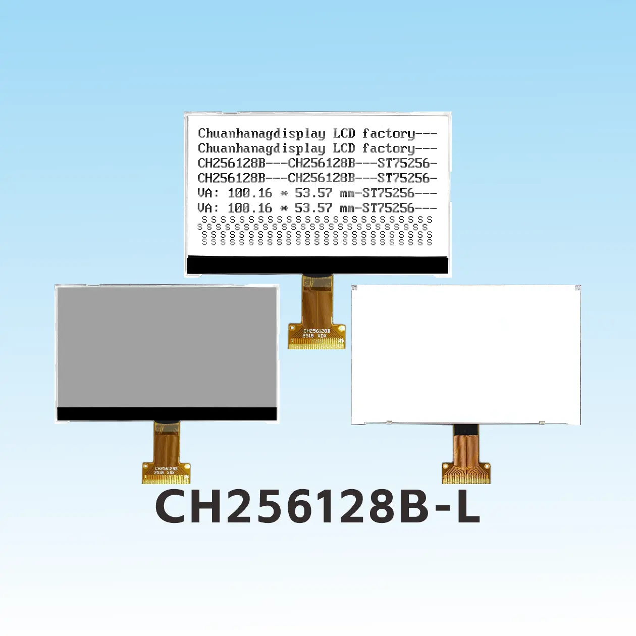
A COG module stands for Chip-on-Glass module. It is a liquid crystal display assembly where the display driver integrated circuit (IC) mounts directly onto the contact ledge of the LCD glass substrate.
This design eliminates the separate PCB carrier that traditional displays require to house the controller. By moving the silicon chip directly onto the glass panel, the display becomes an integrated, ultra-slender component.
The core manufacturing technology behind every cog lcd module is Anisotropic Conductive Film (ACF) bonding. During assembly, the bare driver IC die aligns precisely over transparent Indium Tin Oxide (ITO) traces patterned on the glass.
An ACF layer sits between the IC bumps and the glass pads. Automated bonding equipment applies exact heat and pressure. Microscopic conductive particles inside the adhesive compress vertically, forming solid electrical connections between the IC outputs and the LCD electrodes.
At the same time, the adhesive acts as an electrical insulator horizontally. This prevents short circuits across tight pitch leads, even when lead spacing drops below 30 microns.
A standard chip on glass display consists of four structural elements:
Replacing legacy display configurations with a monochrome COG display or graphic panel provides immediate mechanical and electrical benefits. These features directly affect product durability, assembly costs, and visual performance.
Traditional display modules rely on a thick PCB backing plate. A conventional board adds between 1.6 mm and 3.0 mm of rigid material behind the glass, plus additional depth for soldered pins or elastomeric zebra connectors.
A cog module eliminates this backing board entirely. The total module thickness often drops below 2.0 mm, including the LED backlight. This allows industrial designers to produce sleek, modern enclosures with tighter seals and thinner profiles.
Every additional component in a bill of materials increases procurement risk, inventory holding costs, and manufacturing overhead. A COG setup removes the secondary display PCB, rubber elastomeric strips, and discrete interface connectors.
Modern COG LCD manufacturing relies heavily on automated surface-mount and hot-bar bonding processes. High automation reduces manual labor during final assembly, which yields lower unit costs when producing medium to high production volumes.
Field failures in portable equipment often trace back to broken solder joints and mechanical displacement. Drops, cyclic vibrations, and thermal cycling degrade mechanical connections over time.
Because the IC inside a chip on glass display sits embedded under cured epoxy and bonded with structural ACF, it possesses exceptional shock resistance. There are no long copper leads to fracture, and no rubber zebra connectors to shift out of alignment during physical impacts.
Connecting a display driver through long PCB traces and through-hole pins introduces stray capacitance and electrical impedance. These parasitic effects degrade signal integrity and increase power consumption.
In a cog lcd module, the physical distance between the driver chip outputs and the liquid crystal segments measures only a few millimeters across the ITO layer. Low trace capacitance reduces driver output loading, cutting system power consumption. For battery-powered field instruments, this directly extends operational runtimes.
Selecting the correct display construction requires evaluating form factor constraints, budget targets, and mechanical durability. The table below illustrates the mechanical and manufacturing differences among the three main packaging standards.
| Feature | COG (Chip-on-Glass) | COB (Chip-on-Board) | COF (Chip-on-Film) |
|---|---|---|---|
| Driver Location | Directly on LCD glass substrate | On a secondary FR4 PCB board | Bonded to the flexible polyimide cable |
| Total Thickness | Ultra-thin (typically 1.5 mm – 2.5 mm) | Bulky (typically 6.0 mm – 10.0 mm) | Thin (typically 2.0 mm – 3.0 mm) |
| Mechanical Durability | High; solid-state bonded structure | Moderate; soldered pins can crack | High; flexible interconnects |
| Tooling & Unit Cost | Low tooling; economical in volume | Very low tooling; higher material costs | Higher tooling and raw material cost |
| Primary Suitability | Ultra-compact, battery-powered devices | Large stationary equipment, rack mounts | Curved profiles, bezel-less screens |
When comparing COG vs COB, the difference is night and day for handheld enclosures. COB displays rely on black epoxy "glob-top" drops on an extended PCB. They work fine for vintage desktop instruments, but they are too bulky for modern industrial handhelds.
COF displays solve thickness issues by mounting the IC onto a bendable flex circuit. However, COF tooling costs and raw film expenses remain high. For cost-sensitive, high-durability hardware, COG remains the balanced, industry-preferred choice.
Hardware teams across multiple sectors use COG displays to solve mechanical layout problems without sacrificing readability.
Modern electrical, gas, and water meters operate in harsh outdoor conditions for over a decade on a single lithium battery pack. These devices require display panels that withstand wide temperature swings without drawing excessive sleep current.
Manufacturers use custom segment-type monochrome COG display units to show meter readings, signal strength, and tariff icons. At Chuanhang Display, we supply ruggedized COG panels with specialized polarizers to ensure clear sunlight readability and long-term UV resistance in field environments.
Patient health devices such as blood glucose monitors, digital pulse oximeters, and portable infusion pumps must remain lightweight and easy to disinfect. Thin device profiles allow patients and nurses to carry these tools comfortably.
A graphic cog module provides clean resolution for waveforms, numerical vitals, and battery indicators. The secure bonding ensures that occasional drops onto hospital floors do not disrupt the connection between the display glass and the controller.
Warehouse barcode scanners, point-of-sale (POS) terminals, and digital multimeters operate in rough daily environments. They encounter drops, dust, moisture, and high vibration from manufacturing plants.
A compact LCD display based on COG architecture holds up reliably under continuous mechanical stress. Integrating the driver on the glass frees up space inside the device housing for larger battery packs or secondary scanning antennas.
Automotive center consoles and instrument clusters often feature auxiliary screens for climate control, tire pressure readings, and audio track details. Space behind the dashboard is tight, packed with wiring harnesses and structural supports.
COG displays slide into these tight cavities easily. Automotive-grade driver ICs paired with high-contrast fluid types (such as FSTN or VA) deliver wide viewing angles and deep black backgrounds in both direct sun and nighttime driving conditions.
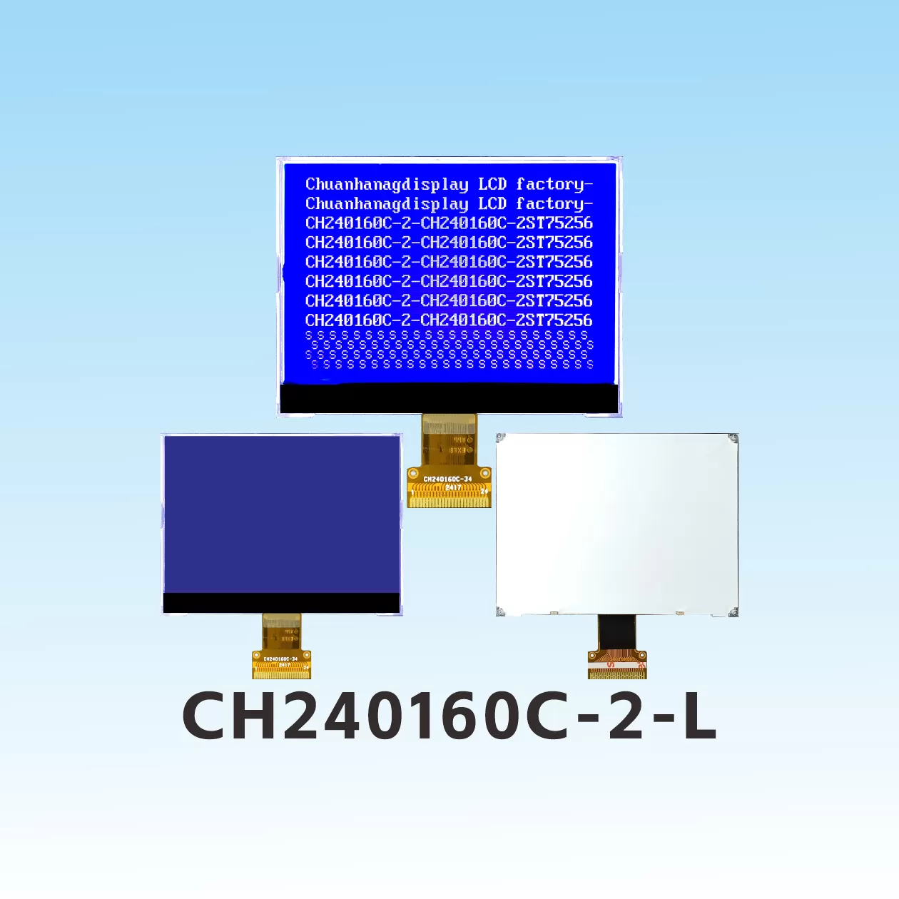
Integrating a cog lcd module into your schematic and mechanical CAD assembly requires careful planning. Keep these three technical parameters in mind during component selection:
COG driver ICs support common digital communication protocols. Your choice dictates pin counts on the FPC and processing load on the host microcontroller:
Standard consumer LCD fluid slows down in freezing conditions and loses contrast in extreme heat. If you design hardware for industrial or outdoor use, select wide-temperature liquid crystal formulations.
Specify displays rated for an operating temperature range of -20°C to +70°C, or an extended industrial range of -30°C to +80°C. Ensure the selected driver IC includes internal temperature compensation circuitry to adjust bias voltages automatically as ambient temperatures fluctuate.
Standard off-the-shelf displays work well for initial proof-of-concept prototypes. However, commercial production runs often benefit from customized tooling.
Customizing a monochrome COG display allows you to tailor active display areas, segment icons, FPC pinouts, and backlight colors precisely to your chassis. Non-recurring engineering (NRE) tooling costs for monochrome glass are modest, and the resulting part eliminates mechanical compromises inside your enclosure.
Q1: Can a damaged COG module be repaired in the
field?
A1: No, a COG module cannot be repaired at the component
level. The driver IC is bonded permanently to the glass substrate using cured
anisotropic conductive adhesive. If the glass cracks or the IC fails due to
electrical overstress, the entire display assembly must be replaced.
Q2: Do COG modules support full-color graphic
displays?
A2: Yes. While the technology is widely known for
monochrome segment and dot-matrix panels, many thin-film transistor (TFT) color
LCDs also use COG architecture to mount source and gate driver chips directly
onto the glass panel.
Q3: How does a COG LCD module compare to an OLED
display?
A3: OLED panels offer higher contrast and self-emissive
pixels, but they consume more power when displaying bright backgrounds and risk
burn-in over long static runtimes. A reflective or transflective monochrome COG
LCD consumes far less power, offers excellent readability in direct sun, and
costs substantially less.
Q4: How do I protect the exposed driver IC on the glass
ledge?
A4: During manufacturing, the driver IC is sealed under a
layer of non-conductive protective silicone or UV-cured resin. When designing
your final enclosure, include a mechanical bezel or silicone gasket that covers
the IC ledge to prevent direct pressure or static discharge onto the silicon
die.
Q5: What is the typical lead time and tooling cost for a custom COG
display?
A5: Custom monochrome COG LCD tooling typically requires 3
to 5 weeks for initial engineering drawings and counter-samples. Tooling costs
are relatively low compared to injection molds, making customized glass an
accessible option even for mid-sized production volumes.
Display technology should never restrict your product design. Choosing a cog module gives your engineering team the mechanical freedom to build slimmer enclosures, reduce internal wiring, and prolong battery life in demanding field applications.
Whether you need a drop-in replacement for an obsolete component or a ground-up custom display layout, Chuanhang Display delivers reliable, production-ready solutions. Contact our engineering support team today to discuss your project requirements, request component datasheets, or order initial evaluation samples.