Monochrome segment liquid crystal displays remain the primary human-machine interface across industrial metrology, medical diagnostics, automotive instrumentation, and ultra-low-power IoT nodes. While graphical thin-film transistor (TFT) panels and OLEDs dominate consumer devices, the custom segment display provides an unmatched balance of micro-ampere current draw, direct sunlight readability, wide thermal tolerances, and sustained production life cycles spanning decades. Designing an application-specific segment panel requires a complete understanding of electro-optical physics, liquid crystal fluid dynamics, multiplex driving topologies, and physical interconnect packaging.
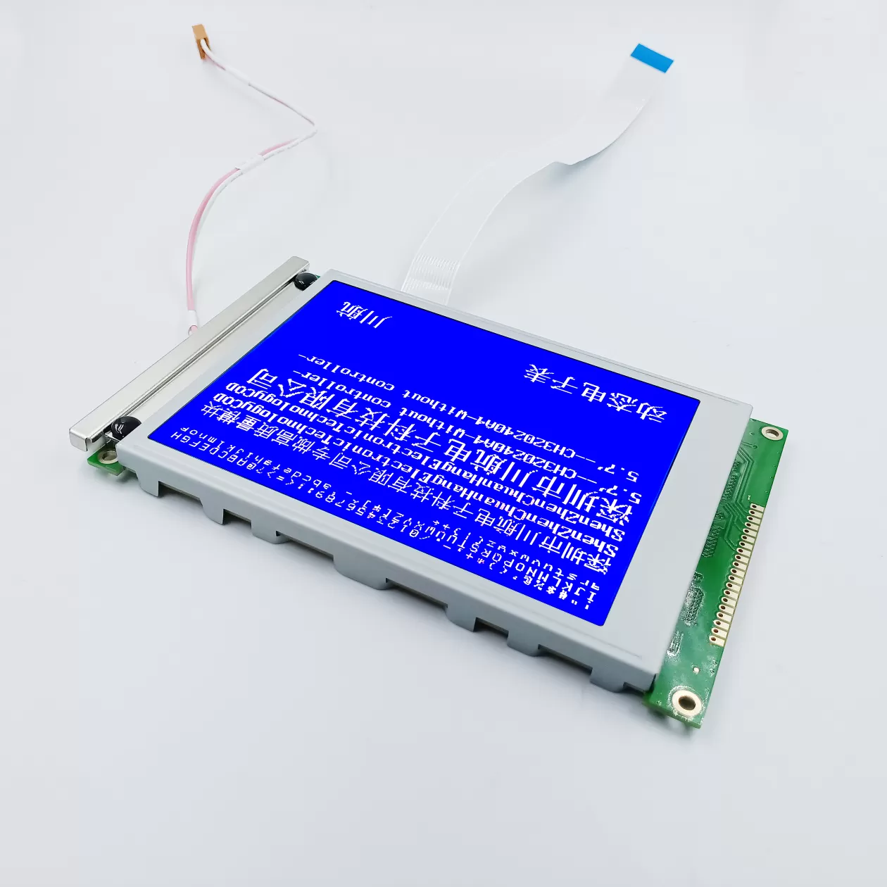
The operational baseline of any custom segment display depends on the liquid crystal mode selected during the layout phase. The interaction between molecular alignment, optical anisotropy (birefringence), and polarizers governs contrast ratio, viewing angles, response latency, and drive voltage constraints.
Twisted Nematic represents the foundational liquid crystal mode. In a TN cell, nematic liquid crystal molecules undergo a 90-degree molecular twist between two parallel glass substrates coated with rubbed polyimide alignment layers. Unenergized ambient light follows the molecular helix, rotates 90 degrees, and passes through the analyzer polarizer. When an electric field exceeds the threshold voltage (typically 1.5V to 3.0V RMS), the molecules reorient vertically along the electric field lines, disabling optical rotation and blocking light transmission.
Contrast Ratio: Typically 5:1 to 10:1 under direct perpendicular illumination.
Viewing Cone: Narrower viewing field (6 o'clock or 12 o'clock viewing angles must be designated at manufacturing tooling).
Response Time: Rapid transition times (20ms to 50ms at 25°C), functioning down to -20°C before viscosity increases significantly.
Driving Compatibility: Optimal for static (direct drive) up to 1/4 duty multiplex configurations.
STN technology increases the molecular twist angle from 180 degrees up to 270 degrees by introducing a chiral dopant into the nematic host material. This pronounced twist steepens the electro-optical transmission curve, allowing the liquid crystal to transition rapidly from an unselected state to a selected state over a tight voltage differential. This steep threshold allows higher multiplex rates (1/8 duty up to 1/32 duty) without loss of optical contrast.
STN displays inherently introduce optical dispersion, creating background color shifts (yellow-green or blue modes). To achieve neutral background characteristics, Film-compensated STN (FSTN) incorporates an optical retardation film between the upper substrate and polarizer. The retardation film compensates for the phase difference introduced by the STN cell, producing a crisp black-on-white or white-on-black image suitable for medical diagnostic displays and precision process meters.
Vertical Alignment, also categorized as Improved Black Nematic (IBN), aligns liquid crystal molecules homeotropically (perpendicular to the substrates) in the unenergized state. In combination with crossed polarizers, VA technology blocks nearly 100% of light leakage in the off state, generating high contrast ratios exceeding 300:1 up to 1000:1.
When energized, negative dielectric anisotropy liquid crystal molecules tilt horizontally, allowing light transmission through dedicated optical sub-pixels. VA panels yield deep, true-black backgrounds and wide viewing cones across all four quadrants. Because VA cells require precise cell-gap tolerances (often 3.0 to 4.0 microns with synthetic micro-pearl spacers) and higher operating voltages (typically 4.5V to 5.0V RMS), engineers specify this mode for premium consumer appliances, marine instruments, and automotive center consoles where optical contrast is paramount.
The choice of front and rear polarizers dictates panel legibility under varied ambient light environments:
Reflective Polarizers: Feature a 100% opaque reflective backing on the rear polarizer. Ambient light enters the front, passes through the liquid crystal cell, reflects off the rear substrate mirror, and exits back to the observer. Reflective panels require zero active backlighting, enabling multi-year operational life on coin-cell batteries (CR2032) in direct sunlight. They cannot be illuminated from behind for dark-environment operation.
Transmissive Polarizers: Include a standard linear polarizer on the rear with no reflective backing. The display requires a continuous backlight source (LED array via a polymethyl methacrylate light guide plate) to be legible. Ideal for negative-mode displays (light digits on dark backgrounds) utilized in indoor medical and audio equipment.
Transflective Polarizers: Combine a partially reflective coating with partial optical transmission. Under strong ambient sunlight, the panel acts as a reflective display; in low-light environments, rear LED backlighting shines through the transflective layer to illuminate the icons. This hybrid approach is common in industrial handheld meters and smart grid infrastructure.
Every custom segment display utilizes patterned Indium Tin Oxide (ITO) conductive traces deposited on the interior surfaces of the glass substrates. The layout of these traces defines whether the module runs via direct static drive or multiplexed matrix drive.
Liquid crystal materials are chemically sensitive to direct current (DC) biasing. Extended exposure to a net DC component across the cell causes electrochemical electrolysis of the alignment layer and ionic migration within the liquid crystal fluid, resulting in irreversible segment burn-in and glass degradation. Therefore, all segment display drivers must supply alternating current (AC) symmetrical square waves with a net DC offset under 50 millivolts.
In a static drive layout, every individual segment or discrete icon on the front substrate connects to an independent drive pin, while the entire rear substrate consists of a single continuous Common (COM) plane. To activate a segment, the driver applies an out-of-phase AC square wave between the selected segment pin and the COM plane, creating an effective root-mean-square voltage ($V_{RMS}$) well above the fluid activation threshold. Unselected segments receive an in-phase square wave, yielding an effective $V_{RMS}$ of zero.
Advantages: Maximizes optical contrast, delivers the widest possible viewing angles, and eliminates ghosting entirely. It generates near-zero electromagnetic interference (EMI).
Disadvantages: High pin count. An 8-digit 7-segment display requires 56 segment pins plus 1 common pin (57 interconnect lines), drastically increasing connector complexity and glass trace density.
To reduce trace density and microcontroller pin counts, multiplexed addressing groups multiple segments onto single pins across several Common planes (COM1, COM2, COM3, COM4, up to COM8 or COM16). Multiplexing relies on driving the liquid crystal at distinct intermediate voltage levels.
Two fundamental parameters define the drive topology:
Duty Cycle ($1/N$): Represents the fraction of time within an electrical frame period that a specific Common line is activated. Common duty configurations are 1/2, 1/3, 1/4, and 1/8 duty.
Bias Ratio ($1/B$): Defines the voltage step increments used to construct the intermediate driving waveform, commonly configured as 1/2, 1/3, or 1/4 bias. A 1/3 bias scheme uses four discrete voltage levels ($V_{DD}$, $2/3 V_{DD}$, $1/3 V_{DD}$, and $V_{SS}$).
The discrimination ratio ($S$), which is the ratio of selected segment RMS voltage ($V_{ON}$) to unselected segment RMS voltage ($V_{OFF}$), determines the maximum achievable contrast before ghosting occurs:
$$S = \frac{V_{ON}}{V_{OFF}} = \sqrt{\frac{\sqrt{N} + 1}{\sqrt{N} - 1}}$$
As the duty cycle ($N$) increases, the ratio $S$ approaches 1, narrowing the voltage margin between an ON segment and an OFF segment. Consequently, high-multiplex designs demand liquid crystal fluids with steep transmission thresholds (such as FSTN) and tight temperature compensation circuits to prevent background ghosting at elevated temperatures or segment washout at sub-zero temperatures.
Transferring electrical drive signals from the PCB to the ITO electrode patterns on the glass requires reliable, mechanically robust interconnect methods. Engineering teams collaborating with manufacturing partners such as Chuanhang Display typically choose between four standard physical interconnect formats:
Solid metal pins (phosphor bronze with pure tin or gold plating) are mechanically crimped directly over conductive ITO contact pads along the ledge of the glass substrate and secured using epoxy resin. Pin pitches are standard 2.54mm (0.1 inch), 2.0mm, or 1.27mm.
Assembly: Through-hole soldered directly to the main system PCB or inserted into SIP/DIP sockets.
Mechanical Integrity: Highly resistant to high-shock and high-vibration industrial environments.
Density Limits: Limited to lower trace densities due to physical pin spacing constraints.
Elastomeric connectors consist of alternating microscopic layers of conductive carbon-impregnated silicone and non-conductive silicone rubber (typically 0.10mm to 0.05mm pitch). The silicone strip is positioned between the display glass ledge and matching gold-plated PCB pads.
Assembly: Requires a rigid mechanical bezel or plastic housing with uniform compressive force (screws or snap tabs) to compress the strip by 10% to 15% of its free height.
Environmental Performance: Highly compliant; absorbs thermal expansion mismatches between FR4 PCB material and soda-lime glass. The silicone seal protects contact points against atmospheric sulfur and oxidation.
Heat seal connectors utilize a flexible polyester (PET) film printed with conductive carbon or silver-graphite ink traces and coated with a thermosetting anisotropic adhesive. The flexible ribbon is bonded between the glass ITO ledge and PCB traces using a heated thermode bar under regulated pneumatic pressure.
Flexibility: Enables versatile mechanical placement; the PCB can be mounted perpendicular, offset, or remote from the display panel.
Considerations: Sensitive to moisture ingress and extreme thermal cycling if peeling stress is applied to the bond line.
In modern high-density custom segment display modules, the LCD controller/driver integrated circuit (IC) is mounted directly to the extended glass ledge using Anisotropic Conductive Film (ACF). Gold bumps on the bare silicon die bond directly to the fine-pitch ITO traces on the glass.
Instead of routing dozens of segment and common lines from the main PCB to the glass, the system microcontroller interfaces with the on-glass driver via standard serial buses (I2C, 3-wire SPI, or 4-wire SPI). This approach reduces the physical connection to a minimal 4- to 8-conductor Flexible Printed Circuit (FPC), freeing PCB routing channels and minimizing board surface area.
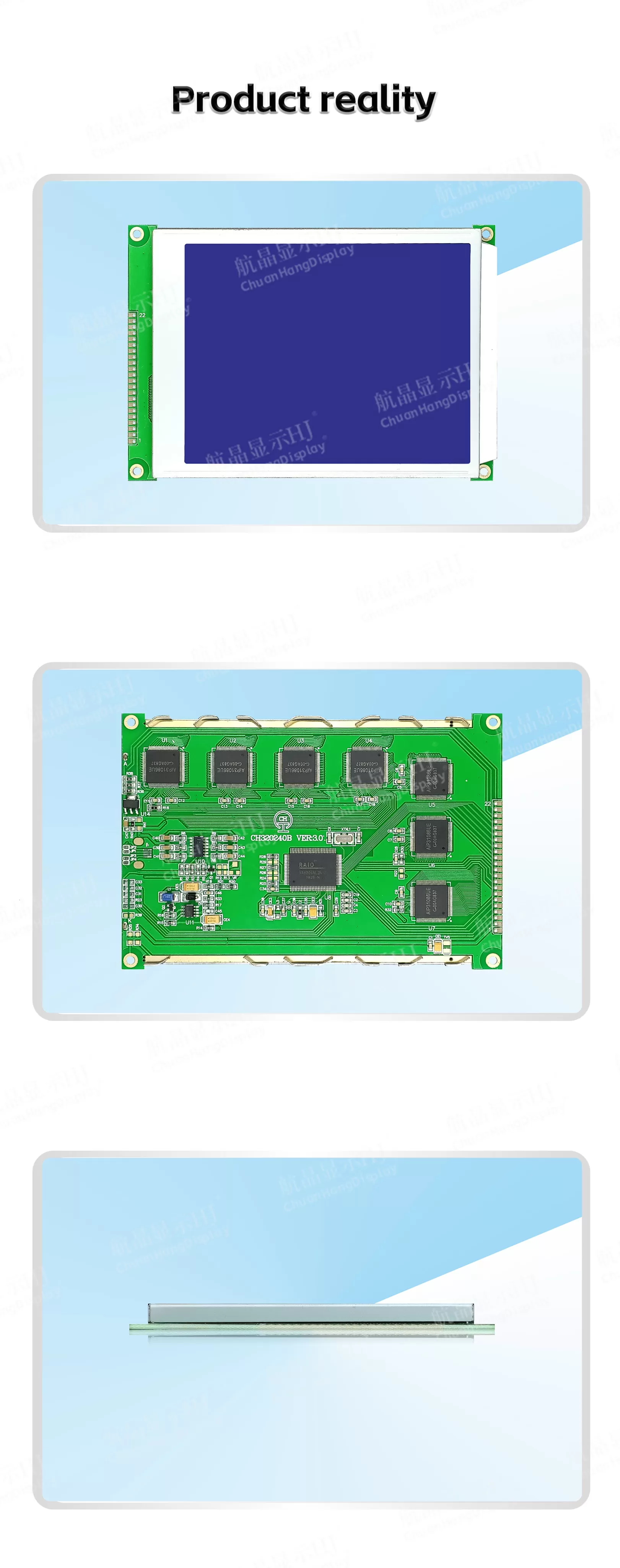
Executing an application-specific segment glass design requires a rigorous stage-gate engineering workflow to ensure visual clarity, electrical compatibility, and long-term supply continuity.
Segment & Icon Layout Design: Detailed CAD drafting of all alphanumeric digits, custom symbols (e.g., battery levels, wireless signal indicators, engineering units like kPa, °C, bar), bar graphs, and annunciators. Non-active border zones, viewing area (VA), and active area (AA) dimensions are fixed.
Multiplex Mapping & Trace Routing: Segments are assigned to designated Common planes and Segment driver outputs. ITO routing widths and cross-over isolations are engineered to maintain uniform trace resistance across the substrate, preventing brightness variances across distinct segments.
Tooling and Photolithography Mask Generation: Precision chrome-on-glass photolithography masks are etched for both upper and lower substrate layers, along with tooling for polarizer cutting dies, polyimide rubbing fixtures, and anisotropic conductive alignment jigs. Engineering teams at Chuanhang Display review trace impedance and fill-factor optimizations during this phase to streamline optical performance.
Sample Prototyping and Optical Characterization: Engineering samples are produced and evaluated across the operating envelope. Key performance metrics measured include cell gap consistency, response time, threshold voltage ($V_{10}$), saturation voltage ($V_{90}$), and the viewing cone using automated optical goniometers.
Mass Production and Environmental Qualification: Following prototype approval, display cells undergo environmental burn-in and qualification tests, including High-Temperature High-Humidity operational storage (e.g., 60°C/90% RH for 500 hours) and thermal shock cycling (-40°C to +85°C).
The duty cycle establishes the time slice allocated to each common line during an electrical frame cycle, while the bias ratio sets the intermediate voltage steps. As the duty cycle increases (e.g., transitioning from static direct drive to 1/8 duty), the voltage difference between an intended active segment ($V_{ON}$) and an inactive segment ($V_{OFF}$) narrows according to the Alt & Pleshko threshold formula. This smaller voltage difference reduces optical contrast and narrows the angle from which the display can be read without ghosting or segment fading. Lower multiplex rates consistently deliver wider viewing angles and higher contrast.
Tooling a custom segment display involves non-recurring engineering charges for several physical assets: photolithography tooling masks for etching top and bottom ITO glass traces, cutting dies for the front and rear polarizers, silkscreen masks for polyimide alignment layers and epoxy perimeter seals, metal pin header stamping molds (if utilizing pin interconnects), and automated testing program jigs. NRE costs for monochrome segment glass are significantly lower than active-matrix TFT mask sets, making custom monochrome panels highly cost-effective even for moderate annual production runs.
Segment displays excel in power consumption, processing overhead, and outdoor optical clarity. A static or low-multiplex segment display running on a 3V power rail draws mere microamperes of current, allowing multi-year operation from a coin-cell battery. Because segments represent dedicated shapes rather than thousands of individual matrix pixels, the host microcontroller requires minimal memory, zero frame-buffer overhead, and simple serial or parallel communication. In harsh optical environments, reflective and transflective segment panels maintain high contrast under direct sunlight without the thermal load or high backlight power draw inherent to TFT panels.
Liquid crystal fluids exhibit temperature-dependent viscosity. As ambient temperatures decrease toward -30°C or -40°C, the fluid's rotational viscosity increases, causing the reorientation of the liquid crystal molecules under an electric field to slow. This manifests as optical latency (sluggish display updates). At extreme positive temperatures, the fluid approaches its isotropic clearing point, where the liquid crystal loses its ordered molecular structure and ceases to modulate polarized light, causing all segments to fade. To handle wide-temperature environments, specialized wide-temp fluid formulations are paired with integrated temperature-compensated drive voltages that dynamically increase $V_{LCD}$ as temperatures fall.
Through-hole metal pin headers soldered directly into a PCB deliver high mechanical retention and electrical stability under continuous, severe vibration (such as automotive engine bays or heavy agricultural machinery). Elastomeric zebra connectors also exhibit high vibration tolerance because the elastomeric silicone absorbs mechanical shocks without fatiguing metal connections, provided the external housing bezel maintains consistent, rigid compression.
Ghosting occurs when an unselected segment partially activates, appearing faintly visible against the background. This typically results from three distinct factors: an incorrect bias voltage setting where the unselected RMS voltage ($V_{OFF}$) exceeds the fluid's threshold voltage ($V_{th}$); elevated ambient operating temperatures lowering the fluid threshold voltage without corresponding driver voltage compensation; or high trace resistance across long, narrow ITO lines causing cross-talk between adjacent common and segment channels. Resolving ghosting requires retuning the driver supply voltage ($V_{LCD}$), selecting a fluid with a steeper electro-optical curve, or optimizing the internal glass ITO trace geometry.
For custom engineering consultations, glass layout evaluations, or high-reliability manufacturing specifications, contact the engineering team at Chuanhang Display to initiate a technical review of your custom segment display project.