Choosing the right display module is one of the most critical hardware decisions you will make during product development. It dictates your enclosure dimensions, internal PCB stack-up, battery life, and your total bill of materials (BOM). A wrong turn can force expensive mechanical redesigns or inflate production costs later.
When engineering an embedded device, medical instrument, or industrial meter, the debate often boils down to two packaging architectures: Chip-on-Glass (COG) and Chip-on-Board (COB). The primary difference lies in where and how the driver integrated circuit (IC) is mounted.
At Chuanhang Display, we have spent over 13 years designing and manufacturing custom monochrome and TFT display panels. We operate dedicated COG and SMT production lines to build dependable visual interfaces. This guide breaks down both technologies to help you specify the right display for your next project.
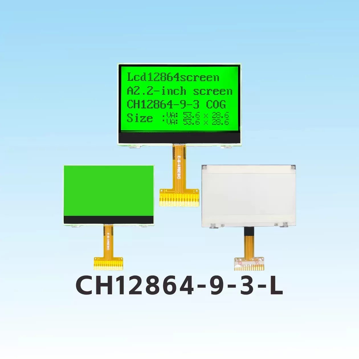
A COG LCD module—short for Chip-on-Glass—mounts the display driver IC directly onto the overlapping contact ledge of the liquid crystal display glass. Instead of using an external printed circuit board (PCB) to house the silicon, the bare die connects to the glass substrate using Anisotropic Conductive Film (ACF).
This direct bonding eliminates the standard underlying circuit board. Electrical connections to the host system run through a flexible printed circuit (FPC) tail bonded directly to the glass substrate. The result is an ultra-compact visual component built for tight physical enclosures.
Ultra-Thin and Lightweight: By removing the thick FR4 PCB substrate, a Chip on Glass display slashes overall module thickness down to around 1.5 mm to 2.0 mm. It cuts hardware weight significantly.
Narrow Bezels and Sleek Aesthetics: The display area sits closer to the outer mechanical edge. This structure allows product designers to build modern, streamlined front panels with minimal border waste.
Lower Power Consumption: Shorter electrical traces between the driver chip and the liquid crystal electrodes reduce trace resistance and parasitic capacitance. This makes the COG LCD module ideal for battery-powered instruments.
Economical at High Volumes: Removing the PCB, elastomeric zebra connectors, and bezel hardware reduces raw material costs during high-volume production runs.
Mechanical Fragility: Because the module consists mainly of glass, it requires thoughtful mechanical support. Shock mounting or structural ribs in your enclosure must isolate the glass from torsional stress.
Higher Upfront Tooling: Custom glass cutting and dedicated FPC tooling can make initial NRE (Non-Recurring Engineering) fees higher compared to using off-the-shelf standard boards.
You will find COG technology widely deployed in handheld medical diagnostic tools, wearable electronics, smart utility meters (water, gas, electricity), and high-end automotive instrument clusters where physical space is at a premium.
Chip-on-Board (COB) is the traditional approach to liquid crystal packaging. In a COB assembly, the display driver IC is mounted directly onto a rigid FR4 PCB using wire bonding. The delicate silicon and microscopic bond wires are then sealed under an epoxy resin droplet, commonly known in the industry as a "black glob."
The LCD glass panel sits above this PCB, joined mechanically by a stamped metal bezel and electrically by elastomeric zebra strips or soldered pins. This design turns the display into an independent, structurally rigid sub-assembly.
Exceptional Mechanical Ruggedness: The rigid PCB acts as a protective shield for the display glass. It absorbs mechanical vibrations and resists external physical impact far better than bare glass.
Simple Enclosure Mounting: Most COB units include standardized mounting holes directly on the PCB corners. Assembly workers can fasten the module directly to an enclosure or chassis using standard machine screws.
Easy Prototyping: Standard 16x2 character displays or 128x64 graphic modules are widely available as off-the-shelf parts with low minimum order quantities.
Straightforward Interfacing: Connections rely on standard through-hole pin headers or simple wire harnesses, which simplifies manual assembly and field replacement.
Bulk and Weight: The combination of a thick PCB, rubber connectors, metal housing, and the glass panel results in a chunky profile, often exceeding 8.0 mm to 10.0 mm in total depth.
Wider Borders: The metal bezel requires significant surface area around the perimeter of the active display area, forcing larger housing dimensions.
COB displays dominate heavy industrial machinery control panels, commercial white goods, laboratory rack units, and outdoor fuel dispensers where mechanical abuse and harsh vibration are daily realities.
Selecting between these two display technologies requires a direct comparison across mechanical, electrical, and commercial parameters. The table below outlines how they match up:
| Parameter | COG LCD Module | COB LCD Module |
|---|---|---|
| Average Thickness | 1.5 mm – 2.5 mm (Extremely Slim) | 7.0 mm – 12.0 mm (Bulky) |
| Module Weight | Minimal (Only glass and thin FPC) | Heavy (FR4 PCB, metal frame, glass) |
| Vibration & Shock Resistance | Moderate (Requires external cushioning) | High (Ruggedized by rigid PCB base) |
| Interconnection Method | FPC cable (ZIF connector or hot-bar soldering) | Through-hole pins, soldered wires, or headers |
| Mechanical Mounting | Adhesive tape, gasket compression, or plastic clips | Direct screw mounting via PCB holes |
| Custom Tooling (NRE) Cost | Moderate to High (Glass mask + FPC tooling) | Low to Moderate (Standard PCB routing) |
| High-Volume Unit Cost | Lower (Fewer physical components) | Higher (Includes cost of PCB and metal bezel) |
| Narrow Bezel Capability | Excellent (Minimal border area required) | Poor (Needs metal bezel retention margin) |
Engineering always involves balancing trade-offs. To settle on the right platform, assess your primary constraints across space, environment, and planned manufacturing volume.
Your enclosure profile is under 15 mm thick: If you are designing sleek handheld products, a COB assembly simply will not fit your CAD model.
Your device runs on battery power: The shorter trace runs and optimized drivers in modern COG solutions help squeeze extra operating hours out of compact lithium-ion or coin-cell batteries.
You plan to produce at scale: When your forecast moves into tens of thousands of units, the BOM savings from eliminating the PCB and metal bezel quickly offset initial tooling expenses.
You want a clean, minimalist front panel: COG panels let active pixels sit close to the bezel edge, giving your product a refined, contemporary look.
Your equipment operates around heavy machinery: If your product faces continuous vibration, dropped tools, or heavy physical impacts, the rigid backing of a COB unit offers peace of mind.
You want to avoid mechanical redesigns: When upgrading an existing legacy system built around standard 16x2 or 20x4 form factors, dropping in an identical COB footprint is the path of least resistance.
You are producing low volumes: If your project needs fewer than 1,000 units per year, avoiding custom glass tooling makes standard COB units the more economical choice.
Assembly must happen without specialized tooling: COB modules can be soldered into place using basic hand tools without requiring zero-insertion-force (ZIF) connectors or hot-bar bonding equipment.
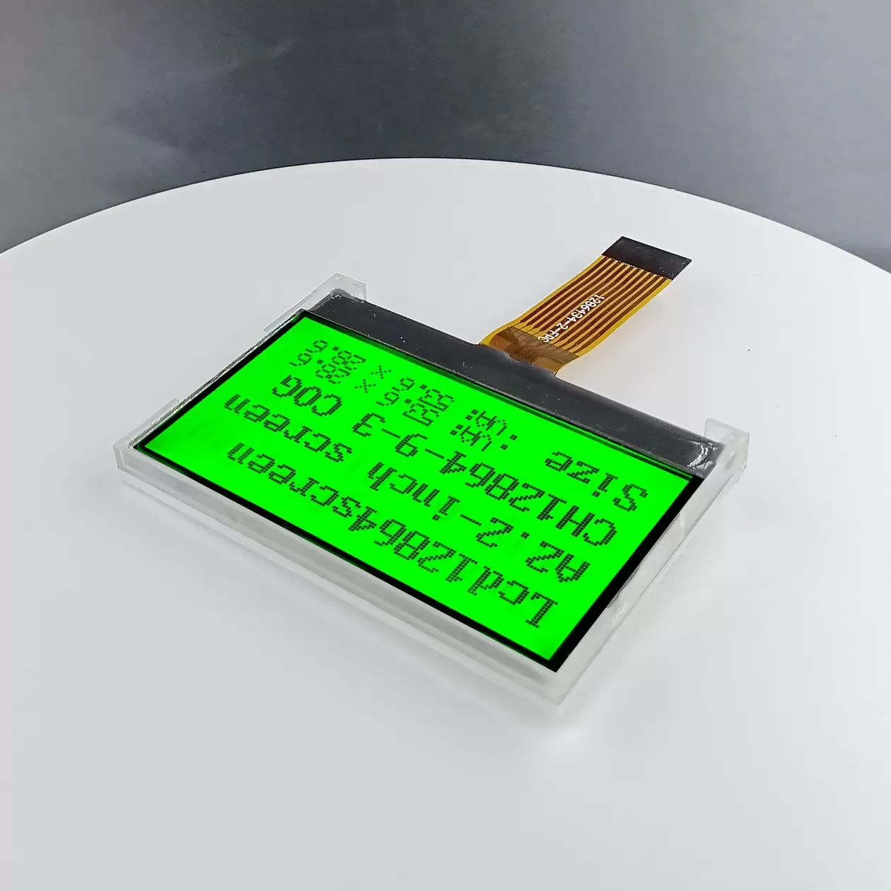
Finding the right balance between design freedom and manufacturing reliability requires a knowledgeable production partner. Founded in 2011, Shenzhen Chuanhang Display Technology Co., Ltd. has established itself as a reliable monochrome LCD module manufacturer and custom display partner for engineers across the globe.
We do not simply resell catalog displays; we build them. Operating out of our 5,000-square-meter modern facility, our workforce of over 100 skilled technicians and a dedicated R&D team of 10+ engineers manage every step of production. Our facilities feature:
Dedicated high-precision COG and FOG bonding lines.
In-house SMT production lines for complete system integration.
Automated COPB and TFT assembly workstations.
Strict cleanroom controls and optical inspection procedures.
Whether you require a custom LCD display featuring specialized segment icons, a high-contrast graphic COG LCD module for a medical monitor, or a heavy-duty industrial LCD screen for factory automation, Chuanhang Display handles your specifications from initial CAD layout to mass production.
Q1: Can a COG LCD module withstand industrial temperature
ranges?
A1: Yes. The operational temperature depends on the liquid
crystal fluid and the bonded driver IC, not the packaging format. Chuanhang
Display manufactures wide-temperature COG modules that operate reliably between
-30°C and +80°C, making them well suited for outdoor and automotive
environments.
Q2: How do you mount a COG display inside an enclosure without screw
holes?
A2: COG panels rely on perimeter mounting techniques.
Engineers typically use precision die-cut double-sided foam adhesives (such as
3M VHB), front silicone gaskets, or custom plastic snap-fit ribs inside the
front housing to secure the glass firmly without creating pressure points.
Q3: Which technology offers better optical
performance?
A3: Optical qualities—such as contrast ratio, viewing
angles, and response times—are governed by the LCD mode (such as TN, STN, FSTN,
or VA) and polarizing films rather than the IC packaging method. Both COG and
COB can deliver identical optical clarity when configured with the same glass
chemistry.
Q4: Why are custom COG displays preferred over standard off-the-shelf
modules?
A4: Custom COG panels let engineers define the exact
physical size, active area, pinout direction, and segment iconography needed for
their specific application. This approach eliminates wasted PCB space and avoids
paying for unused display driver pins or features.
Q5: What is the typical lead time for a custom COG LCD development
project?
A5: Developing a custom display layout, engineering
drawings, and tooling molds typically takes 15 to 20 working days. After the
customer approves physical counter-samples, mass production usually completes
within 4 to 6 weeks, depending on the component volume.
Balancing thickness, structural rigidity, production volume, and system cost will point you toward either COG or COB architecture. If your priority is a slim, power-efficient, and cost-optimized system for volume production, a COG LCD module is hard to beat.
The engineering team at Chuanhang Display is ready to review your mechanical drawings, evaluate your power budgets, and provide sample displays tailored to your product specifications.
Ready to start your display design? Contact the Chuanhang Display technical team at info@scjhdlcd.com to request a design review, product samples, or a project quotation today.