In modern industrial electronics, space optimization, energy efficiency, and cost predictability are key drivers in product development. As microcontroller-driven systems shrink and functional requirements increase, packaging technologies for displays must adapt. Among the prominent technologies utilized in character and graphic displays, the Chip-on-Glass (COG) architecture stands out as a highly efficient packaging method.
This technical guide provides a deep analysis of the COG LCD Module, examining its architectural principles, material components, manufacturing processes, and integration challenges. It serves as a resource for product design engineers, procurement specialists, and system integrators seeking to optimize display configurations. Industrial display manufacturers like Chuanhang Display provide high-quality monochrome and thin-film transistor (TFT) options designed to meet these exacting specifications.
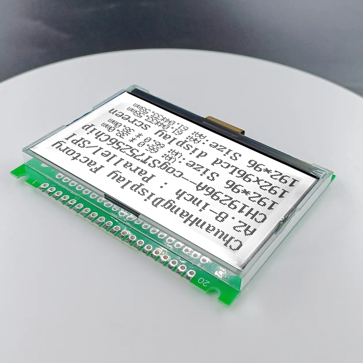
The core concept of a COG LCD Module involves the direct mounting of the display driver integrated circuit (IC) onto the margins of the liquid crystal display glass substrate. This contrasts sharply with older display packaging methods, such as Chip-on-Board (COB) or Chip-on-Film (COF).
In traditional COB designs, the driver IC is packaged in a surface-mount device (SMD) housing or as a bare die wire-bonded onto a separate printed circuit board (PCB) located behind or adjacent to the LCD panel. Connection between the PCB and the glass is then established via elastomeric zebra connectors or heat-seal connectors. While robust, COB displays are bulky, heavy, and have high profile heights.
In a COG LCD Module, the separate PCB is minimized or entirely eliminated for driving purposes. The driver IC chip is flipped and bonded directly to the Indium Tin Oxide (ITO) patterned tracks on the extended lower glass shelf of the LCD panel. The outer leads from the IC are then connected directly to the external system controller via a Flexible Printed Circuit (FPC) or metal pins, yielding several physical and electrical advantages:
A standard COG LCD Module is an assembly of several highly integrated materials. Each component must be carefully specified during the design phase to ensure compatibility with environmental and mechanical requirements.
The module consists of two main glass layers: the thin-film transistor (TFT) or active/passive matrix front substrate, and the color filter or common electrode back substrate. The glass material is typically soda-lime glass or high-purity borosilicate glass. The lower glass substrate is intentionally cut longer than the upper glass to create an exposed shelf. This shelf serves as the mounting platform for the bare silicon driver IC and the input interface connections.
ITO is a transparent, conductive material sputtered onto the glass substrate. Photolithographic etching creates the display electrodes and the routing traces leading to the driver IC bonding area. The pitch (spacing) of these ITO traces must be extremely fine, often down to tens of micrometers, to accommodate high pin-count driver ICs. Sheet resistance of the ITO layers must be carefully managed; higher resistance can lead to signal attenuation and degradation of display contrast, particularly in larger graphic arrays.
The driver IC functions as the bridge between the host microcontroller unit (MCU) and the liquid crystal cells. In a COG configuration, the IC is utilized as a bare die (flip-chip) with gold bumps deposited on its active pads. These gold bumps provide the mechanical and electrical contact points to the ITO terminals on the glass substrate.
ACF is the primary bonding agent used to attach and connect the driver IC to the glass shelf. It consists of an epoxy adhesive matrix embedded with microscopic conductive particles (typically gold-plated plastic or nickel spheres, 3 to 5 micrometers in diameter). During the thermal compression bonding process, pressure is applied to compress the conductive particles between the gold bumps of the IC and the ITO terminals on the glass. This establishes conductive paths along the vertical Z-axis, while the uncompressed particles in the horizontal X-Y plane remain insulated within the adhesive matrix, preventing short circuits between adjacent pads.
An FPC is bonded to the input terminals of the glass shelf to carry power, ground, and control signals (such as SPI, I2C, or parallel interfaces) from the host system. The FPC is usually composed of a polyimide base film with copper traces, finished with gold plating to prevent oxidation and facilitate reliable thermal compression bonding to the ITO glass pads.
The manufacturing process of a COG LCD Module requires high-precision automated assembly equipment. The placement accuracy of the driver IC on the glass substrate is vital; alignment tolerances are typically within +/- 3 micrometers.
The sequence begins with the application of the ACF tape onto the designated bonding area of the glass shelf. The bare driver IC die is picked up by a high-vacuum thermal head, which precisely aligns the gold bumps of the IC with the corresponding ITO pads on the glass using advanced vision alignment systems.
Once aligned, the thermal head descends to perform the main bonding step. This process requires precise control over three primary parameters:
Following the IC bonding process, a secondary bonding step is performed using a similar ACF process to connect the input FPC to the outer terminals of the glass shelf. Finally, a protective silicone or UV-curable resin sealant is applied over the driver IC die and the exposed ITO traces. This passivation layer prevents moisture ingress and mechanical damage to the delicate electrical interfaces.
Choosing a COG LCD Module offers significant spatial advantages and design benefits for industrial, medical, and consumer electronics. Understanding these characteristics helps hardware design teams optimize product architectures.
The elimination of high-profile external components makes COG modules structurally stable. Because the driver IC is bonded directly to the rigid glass substrate and encapsulated under a protective resin barrier, it is highly resistant to mechanical shock and vibration. This makes it suitable for marine instrumentation, agricultural machinery controllers, and hand-held diagnostic tools.
Although the initial tooling costs (Non-Recurring Engineering or NRE) for a custom COG module can be relatively high due to the precision photolithography required for fine-pitch ITO glass patterning, the per-unit cost in medium-to-high volume production is generally lower than that of COB modules. The reduction in raw material components—such as secondary PCBs, connectors, and discrete components—lowers manufacturing and assembly costs.
With profile thicknesses often under 2.0 mm (excluding backlighting), COG modules fit into tight enclosures. Designers can route other system components directly behind the display glass, maximizing internal chassis space. As a specialized manufacturer, Chuanhang Display delivers tailored engineering support to ensure these compact dimensions integrate with your mechanical housing constraints.
Despite its benefits, integrating a COG LCD Module presents specific engineering challenges that must be addressed during the initial product design phases.
Unlike COB modules, where the driver IC can dissipate heat through a larger FR4 PCB copper plane, the driver IC in a COG module is mounted on glass, which has low thermal conductivity. If the display is driven at high refresh rates or high voltage bias configurations, localized heating can occur. This can affect the liquid crystal fluid, potentially causing visual artifacts, contrast degradation, or clearing of the liquid crystal state. Designers should select driver ICs with low power consumption and ensure the system enclosure provides passive ventilation.
The interface between the FPC, the driver IC, and the glass shelf is vulnerable to electrochemical corrosion if exposed to moisture and ionic contaminants under bias voltage. To prevent this, manufacturers apply a robust silicone gel or epoxy coating over the active bonding area. For outdoor or marine applications, specifying high-reliability potting materials or optical bonding of the display faceplate is recommended to prevent moisture condensation.
Because the driver IC is placed directly on the edge of the glass substrate, it is highly susceptible to Electrostatic Discharge (ESD) entering through the display bezel or the touch panel interface. It is important to design adequate grounding paths around the display perimeter. Connecting the metal bezel of the backlight housing to the system chassis ground, and placing ESD protection diodes on the FPC signal lines, helps safeguard the sensitive driver IC from electrical overstress.
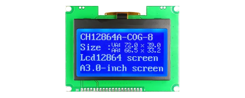
Due to their space-saving architecture and reliability, COG displays are widely used in several key industries:
When selecting a COG LCD Module vendor, engineering teams should evaluate specific technical capabilities rather than focusing solely on unit cost. The quality of the display depends heavily on the precision of the glass patterning, ACF bonding consistency, and environmental testing protocols.
When evaluating a COG LCD Module for new product development, consider the following parameters:
| Parameter | Specification Spectrum | Engineering Implications |
|---|---|---|
| Display Technology | TN, STN, FSTN, DFSTN, TFT | Determines viewing angles, contrast ratios, and color depth requirements. |
| Operating Temperature | Standard (-20°C to +70°C) / Wide (-30°C to +80°C) | Ensures liquid crystal response times remain stable in extreme environments. |
| Interface Types | I2C, SPI, 8-bit Parallel, RGB | Affects pin allocation on the host MCU and display refresh rate limits. |
| Backlight Configurations | LED Side-lit (White, Yellow-Green, Amber, RGB) | Determines legibility in direct sunlight or dim environments; impacts power budget. |
Customization options usually involve modification of the FPC length and routing path, custom backlight brightness levels, touch panel integration (resistive or capacitive), and custom polarizers (transflective, transmissive, or reflective). Working with responsive partners like Chuanhang Display helps ensure these technical requirements are accurately translated into production-ready specifications.
Q1: What is the main difference between COB and COG LCD modules?
A1: The main difference lies in where the driver IC is mounted. In a COB (Chip-on-Board) module, the IC is packaged or wire-bonded onto a secondary PCB at the back of the display. In a COG (Chip-on-Glass) module, the bare driver IC is bonded directly onto the glass substrate of the display itself. This eliminates the secondary PCB, resulting in a significantly thinner and more reliable assembly.
Q2: Can a COG LCD Module operate under extreme outdoor temperature conditions?
A2: Yes, COG modules can be designed for wide temperature operation, typically ranging from -30°C to +80°C. To ensure reliable performance at these extremes, specify wide-temperature liquid crystal fluids to prevent slow response times in cold conditions or clearing in hot environments. High-quality adhesive resins should also be used to maintain ACF bonding integrity.
Q3: How is the driver IC protected from external mechanical damage in a COG display?
A3: After the thermal compression bonding process, a protective, cured epoxy or UV-silicone sealant is applied over the driver IC die and its surrounding conductive connections. This material forms a protective barrier against physical abrasion, dust, and moisture ingress.
Q4: What interface options are typically available for graphic COG displays?
A4: Graphic COG displays typically support serial interfaces such as I2C and 3-wire/4-wire SPI, as well as 8-bit or 16-bit parallel interfaces. Serial interfaces are widely used because they require fewer input pins from the host microcontroller, simplifying FPC routing and system design.
Q5: What are the key factors affecting the tooling costs (NRE) of custom COG displays?
A5: Tooling costs for custom COG displays are primarily driven by the photolithography masks required to etch custom ITO glass traces, the design of custom segment/icon layouts, and the design and tooling of custom FPCs. While these setup costs are higher than standard off-the-shelf displays, they are often offset by lower per-unit costs at production volumes.
Successfully integrating a display panel into your device requires careful evaluation of electrical interfaces, optical properties, and environmental tolerances. To optimize your display configurations, selecting a high-performance COG LCD Module is a collaborative process between your engineering team and your display manufacturing partner.
Whether your design calls for high-contrast monochrome character displays or custom high-resolution graphic arrays, consulting with technical representatives at Chuanhang Display helps streamline the development process, minimize risk, and ensure long-term component availability.
Contact Us Today: If you are currently designing or sourcing a COG LCD Module for your latest project, send us your technical drawings, interface specifications, or project requirements. Submit an inquiry today to receive detailed technical feedback and a comprehensive quotation from our engineering team.