While high-resolution, full-color TFT modules dominate the consumer electronics market, a vast segment of the industrial, medical, and test-equipment sectors relies on robust, low-bandwidth alphanumeric screens. At the forefront of this category is the jhd162a lcd display. Characterized by its 16x2 matrix (displaying 16 characters across two lines), this specific module is a staple in embedded systems due to its high reliability, low power consumption, and minimal processing overhead.
For hardware engineers and B2B procurement teams, sourcing a reliable alphanumeric module involves more than checking a basic datasheet. This article provides a highly technical breakdown of the architecture, material selection, communication protocols, and supply chain dynamics required to successfully source and integrate these displays into professional hardware.
The internal architecture of the module dictates how the host microcontroller (MCU) interacts with the visual interface. Standardizing the communication pipeline is paramount for software development and long-term hardware maintenance.
The functional brain driving the jhd162a lcd display is typically a Hitachi HD44780 compatible controller, or equivalent silicon like the KS0066U or SPLC780D. These integrated circuits handle the complex timing required to multiplex the row and column drivers of the liquid crystal matrix.
The controller manages three distinct memory sectors:
DDRAM (Display Data RAM): Stores the ASCII values of the characters currently rendered on the screen. The DDRAM has 80 bytes of memory, meaning it can store more characters than the 32 visible on a 16x2 screen, allowing for text scrolling functions. CGROM (Character Generator ROM): Contains the permanent bitmaps for standard characters (ASCII, Japanese Kana, and some Cyrillic or European symbols). Each character is generated within a 5x8 or 5x10 pixel dot matrix. CGRAM (Character Generator RAM): Provides 64 bytes of volatile memory, allowing engineers to design up to eight custom 5x8 pixel characters—such as proprietary battery icons, temperature degree symbols, or directional arrows.
The optical clarity of an alphanumeric module heavily depends on the fluid chemistry and polarizer layers used during fabrication.
STN (Super-Twisted Nematic): This is the baseline technology for most 16x2 modules. The liquid crystal molecules have a twist angle of 180 to 270 degrees. While cost-effective, STN panels often exhibit a yellow-green or bluish background and have a restricted viewing cone. FSTN (Film-compensated STN): For applications requiring high contrast—such as medical infusion pumps or precision laboratory scales—FSTN adds an optical retardation film to the STN cell. This eliminates the color tint, producing sharp black pixels on a silver or white background, drastically improving the contrast ratio and viewing angles.
Physical integration of the jhd162a lcd display into a mainboard relies on a standardized 16-pin header. Understanding this interface allows hardware teams to optimize routing on their Printed Circuit Boards (PCBs).
The parallel interface is mapped as follows:
Pins 1 & 2 (VSS, VDD): Power supply connections, typically requiring a stable 5.0V or 3.3V logic level. Pin 3 (V0): Contrast adjustment input, operated via an external potentiometer or a PWM signal smoothed by a low-pass filter. Pins 4, 5 & 6 (RS, R/W, E): Control lines. Register Select (instruction vs. data), Read/Write (usually pulled to ground for write-only operations), and the Enable pin which triggers the data latching process. Pins 7 to 14 (D0 - D7): The bidirectional data bus. Pins 15 & 16 (A, K): Anode and Cathode for the LED Backlight Unit.
To conserve General Purpose Input/Output (GPIO) pins on the host MCU, engineers rarely use the full 8-bit data bus. The controller can be initialized in 4-bit mode, requiring only D4-D7, along with RS and E, reducing the necessary GPIO count from ten down to six.
For maximum pin efficiency, hardware developers frequently pair the display with an I2C expander IC (such as the PCF8574). This "backpack" module converts serial I2C data into parallel data for the display, reducing the connection requirement to just four wires: VCC, GND, SDA (Serial Data), and SCL (Serial Clock).
The Backlight Unit (BLU) determines the power footprint and readability of the display in varying ambient light conditions.
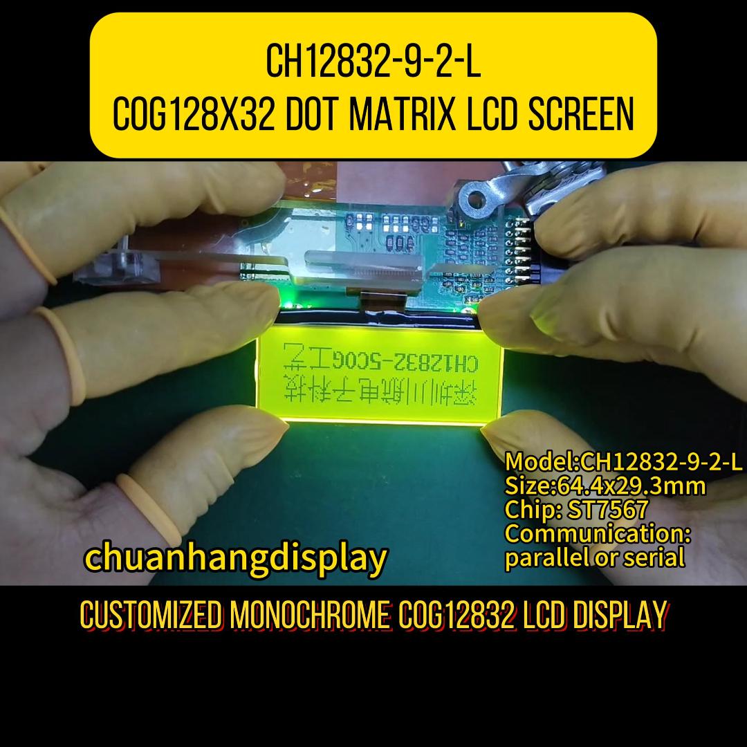
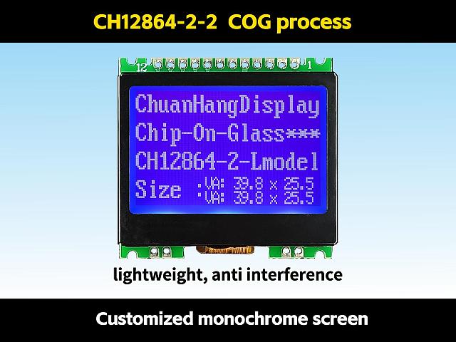
Yellow-Green LED: Often paired with a transflective rear polarizer. This setup is highly resilient because the display remains fully readable under direct sunlight using ambient light reflection, and the LED is only necessary in dark environments. White/Blue LED: Utilizes a transmissive polarizer. The blue background with white characters offers a modern, high-contrast aesthetic highly favored in server rack equipment and consumer audio interfaces. However, it relies entirely on the backlight to be legible.
Managing the thermal output and current draw of pins 15 and 16 requires a properly calculated series resistor to prevent LED degradation, thereby ensuring the module achieves its typical 50,000-hour Mean Time Between Failures (MTBF).
Why do product managers continue to select the jhd162a lcd display over modern graphical alternatives? The primary driver is architectural simplicity combined with extreme physical robustness.
In industrial automation, programmable logic controllers (PLCs) often operate in environments with high electromagnetic interference (EMI). High-speed MIPI or LVDS TFT displays are highly susceptible to noise without heavy shielding. The parallel interface and slow clock speeds of alphanumeric displays make them practically immune to EMI disruptions.
Furthermore, integrating graphical libraries (like TouchGFX or LVGL) requires substantial Flash memory, RAM, and a high-speed ARM Cortex processor. Conversely, driving a 16x2 module requires mere bytes of memory, allowing it to be managed by an inexpensive 8-bit MCU. Specialized manufacturers like Chuanhang Display provide highly optimized, industrial-grade versions of these modules specifically designed to withstand the vibrations, thermal shocks, and continuous operational cycles demanded by heavy industry.
When sourcing a jhd162a lcd display, procurement teams must navigate several supply chain nuances to avoid costly manufacturing defects.
Counterfeit Controller ICs: The market is saturated with unbranded, cloned driver ICs that fail to meet strict HD44780 timing specifications. This results in missing characters, initialization failures, or screen flickering at temperature extremes. Validating the silicon origin is paramount. Backlight Bleeding and Inconsistency: Poor assembly of the metal bezel and the light guide plate (LGP) can lead to bright spots at the edges of the display. Anisotropic Conductive Film (ACF) Degradation: The connection between the internal PCB and the glass substrate utilizes zebra connectors (elastomeric connectors). Substandard compression by the metal bezel can cause rows or columns of pixels to drop out over time.
The Bill of Materials (BOM) cost for alphanumeric modules is inherently low, but extreme cost-cutting compromises the zebra connectors and polarizer films. Working with established vendors such as Chuanhang Display ensures that procurement teams receive transparent documentation regarding component origins, guaranteeing stable yield rates during mass assembly. Lead times for standard variations are typically short, but securing reliable, long-term supply requires clear Minimum Order Quantity (MOQ) agreements to buffer against global silicon fluctuations.
Before approving a vendor for mass production, engineers must subject sample units to rigorous laboratory validation. A reliable supplier should provide detailed testing reports covering:
High Temperature Operating Life (HTOL): Operating the unit at +70°C for 240 hours to check for liquid crystal degradation (darkening of the screen). Low Temperature Storage: Exposing the module to -30°C to ensure the liquid crystal fluid does not freeze and rupture the Indium Tin Oxide (ITO) glass substrate. Vibration Testing: Confirming that the metal tabs securing the bezel to the PCB do not fatigue, which would release pressure on the elastomeric connector and cause display failure.
Procuring from facilities operated by Chuanhang Display guarantees adherence to these strict quality assurance frameworks, preventing field failures and costly product recalls.
Despite the rapid advancement of display technology, the jhd162a lcd display remains an indispensable component in B2B hardware engineering. Its unmatched stability, low resource consumption, and immunity to harsh environmental interference solidify its place in industrial, medical, and commercial infrastructure. By thoroughly understanding the IC architecture, optical materials, and quality control metrics outlined above, procurement teams and design engineers can establish robust supply chains, ensuring their end products function flawlessly for decades in the field.
Q1: What is the standard operating voltage for the jhd162a lcd display?
A1: The module is historically designed for 5.0V logic. However, many modern suppliers offer 3.3V compatible versions by integrating an internal charge pump circuit (like the ICL7660) to generate the negative voltage required to drive the liquid crystal fluid, making it compatible with 3.3V ARM microcontrollers.
Q2: My display lights up, but I only see a row of solid black blocks. How do I fix this?
A2: This is the most common initialization issue. It almost always indicates a problem with the contrast voltage on Pin 3 (V0). You must connect a 10k potentiometer between VDD and GND, with the wiper connected to Pin 3. Adjusting this potentiometer will tune the contrast until the characters become clear. If the contrast is tuned correctly and blocks remain, the MCU has not successfully sent the initialization sequence.
Q3: Can the module display languages other than English?
A3: Yes, but it depends on the specific CGROM mask burned into the controller IC at the factory. The standard HD44780A00 mask contains ASCII and Japanese Kana characters. To display Cyrillic, European accented characters, or custom symbols, you must either source a module with a specific ROM mask or utilize the CGRAM to manually draw up to eight custom characters.
Q4: What is the difference between a Transmissive and a Transflective polarizer on this module?
A4: A transmissive polarizer blocks background ambient light, meaning the display is completely unreadable unless the LED backlight is powered on (common in blue background/white text modules). A transflective polarizer reflects ambient light back out, allowing the display to be perfectly readable in direct sunlight without the backlight, while still allowing the LED backlight to shine through in dark environments.
Q5: How can I reduce the number of pins required to control the display?
A5: First, you can initialize the display in 4-bit mode instead of 8-bit mode, tying the R/W pin to ground, which requires only 6 GPIO pins on your MCU. To reduce it further, you can solder an I2C interface backpack (using an IC like the PCF8574) onto the 16-pin header. This converts the interface to the I2C protocol, requiring only 2 data pins (SDA and SCL) plus power and ground.