Hardware engineers face constant pressure to reduce system footprint while maintaining clear visual readouts. Traditional display formats often force compromises between mechanical thickness, power budgets, and durability. The modern COG module solves this trade-off by eliminating rigid structural layers.
At Chuanhang Display, we work with development teams migrating legacy equipment to compact, energy-efficient interfaces. This technical guide outlines how Chip-on-Glass technology functions, evaluates its trade-offs against legacy packaging, and details the specifications required to source the correct display for industrial builds.
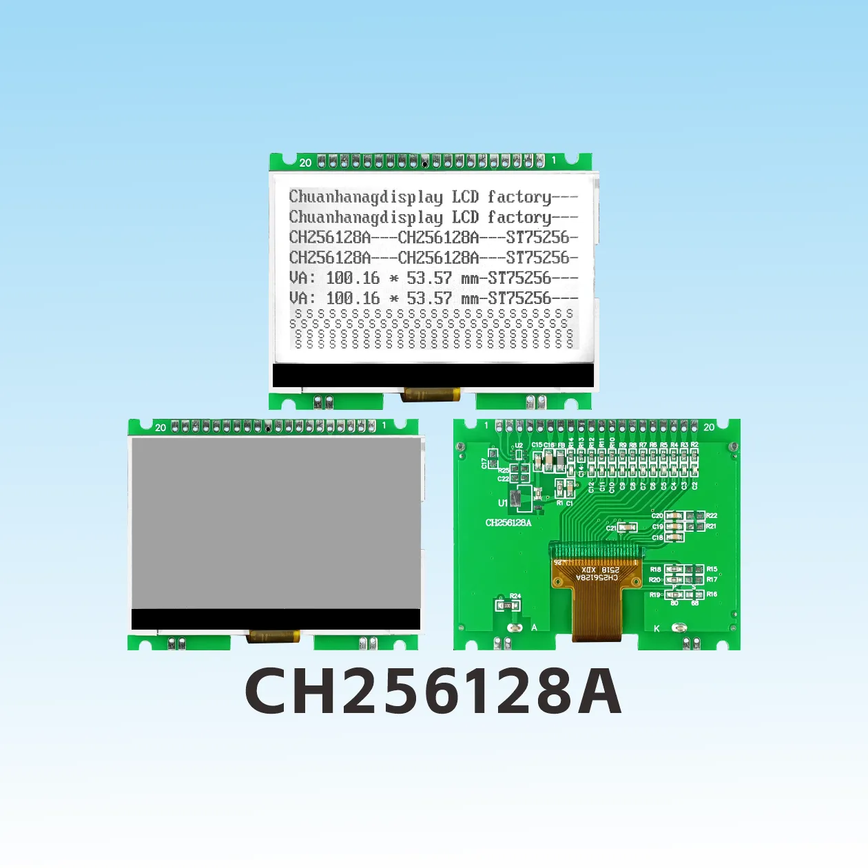
A COG module is a liquid crystal display architecture where the silicon display driver IC mounts directly onto the contact ledge of the LCD glass substrate. Traditional displays solder a packaged driver IC onto an external Printed Circuit Board (PCB). Chip-on-Glass technology removes that dedicated carrier board entirely.
Microscopic Indium Tin Oxide (ITO) tracks are sputtered directly onto the glass panel. The bare driver IC—supplied as a silicon die with gold bumps—mounts face-down onto these transparent conductive tracks. Electrical contact occurs via Anisotropic Conductive Film (ACF). A flexible flat circuit (FPC) then routes control signals straight from the glass edge to your main system motherboard.
By removing the secondary driver PCB, the monochrome COG module cuts module thickness by more than half. It also drops component count and eliminates solder fatigue points common to leaded IC packaging.
Understanding the internal stack helps hardware teams identify failure points during prototyping. A typical Chip-on-Glass LCD consists of five mechanical and electrical elements:
LCD Glass Substrate: Two flat sheets of thin borosilicate glass sandwiching liquid crystal material, internal spacers, transparent ITO routing, and external polarizing films.
Bare Driver IC: An unpackaged silicon die featuring micro-pitch gold bumps across its perimeter, functioning as row and column segment drivers.
Anisotropic Conductive Film (ACF): An adhesive matrix containing conductive nickel-gold coated polymer microspheres that bridge the IC bumps to the ITO glass traces.
Flexible Printed Circuit (FPC): A polyimide tail carrying power lines (VDD, VSS), booster capacitors, and digital control lines directly to the host board.
Backlight Assembly: An edge-lit acrylic light guide plate (LGP) powered by low-current white, yellow-green, or blue LEDs within an ultra-thin plastic housing.
Assembly precision dictates the lifespan and field reliability of any COG module. Because human hands cannot align micro-pitch silicon dies to transparent ITO pads, automated cleanroom equipment carries out the entire packaging sequence.
The manufacturing flow centers on three controlled stages:
An automated tape head applies ACF film across the glass contact ledge under light heat and pressure. The film remains non-conductive along the X-Y plane while insulating adjacent ITO tracks spaced only tens of microns apart.
High-resolution optical alignment systems detect fiducial marks on both the silicon die and the glass ledge. The machine positions the driver IC gold bumps over the matching ITO pads with an alignment tolerance tighter than ±3 microns.
A heated bonding head applies uniform pressure (typically 60 to 100 MPa) and elevated temperature (180°C to 210°C) for several seconds. The adhesive matrix flows, cures, and traps the conductive micro-spheres under compression between the gold bump and the ITO track. This completes the Z-axis electrical connection.
Poor thermal uniformity or uncalibrated head pressure during this cycle causes intermittent lines, high contact resistance, or cracked glass. Experienced teams like Chuanhang Display maintain strict thermal profile logging on all automated thermo-compression bonders to verify joint integrity before shipping.
Selecting between a COG module and a conventional Chip-on-Board (COB) display defines your device enclosure, mold tooling, and long-term serviceability. The following engineering comparison breaks down the trade-offs:
| Engineering Metric | COG Module (Chip-on-Glass) | COB Module (Chip-on-Board) |
|---|---|---|
| Total Module Thickness | 1.5 mm to 2.5 mm (ultra-slim profile) | 8.0 mm to 12.0 mm (chunky due to PCB + bezel) |
| Mechanical Weight | Minimal; relies solely on glass weight | Heavy; requires FR4 carrier board and metal frame |
| PCB Tooling (NRE) | Lower upfront tooling cost; no display PCB needed | Higher PCB fabrication and stencil setup costs |
| Vibration & Shock Tolerance | High; low mass prevents shearing under drops | Moderate; large PCB mass stresses mounting screws |
| Design Flexibility | FPC tail can bend around internal plastics | Rigid board demands fixed interior clearance |
| Field Repairability | Module replacement only | Component-level rework occasionally possible |
| Low-Volume Unit Cost | Higher for small custom batches | Lower for standard 16x2 off-the-shelf formats |
Why do system architects switch to Chip on Glass technology when building handheld or battery-operated systems? The gains go well beyond outward appearance.
In handheld instruments, Z-axis height dictates the user experience. By dropping the external FR4 substrate and metal mounting frame, a COG module trims up to 60% of the display assembly thickness. This permits slimmer industrial housings, smaller battery bays, or added internal shielding without inflating external dimensions.
Monochrome COG units pair static or passive STN/FSTN glass with integrated driver chips that include built-in charge pumps and bias generators. Drawing microamps in standby mode, these panels wake up instantly to refresh data. They preserve battery life far better than power-hungry thin-film transistor (TFT) color panels or active OLEDs that continuously bleed power.
Modern COG modules break out flexible communication buses through their FPC connection. Hardware engineers can talk to the integrated controller using 3-wire or 4-wire SPI, standard I2C, or 8-bit parallel lines (8080/6800 mode). Utilizing an I2C or SPI monochrome COG module reduces the microcontroller pin count to as few as two to four lines, preserving GPIOs for sensors, relays, and communication transceivers.
Because they withstand rough handling and draw minimal current, COG panels serve critical roles across demanding market sectors.
Factory environments expose electronics to mechanical shock, motor-induced EMI, and broad temperature swings. DIN-rail controllers, smart kilowatt-hour meters, and portable field calibration devices use wide-temperature FSTN COG panels that operate reliably from -20°C to +70°C without sluggish response times.
Home healthcare products demand extreme legibility alongside long battery shelf life. Devices such as blood glucose monitors, digital nebulizers, and automated blood pressure cuffs rely on custom COG display formats with custom icons and bold numeric readouts to ensure unambiguous operation by patients.
Gas, water, and heat meters frequently run on a single lithium thionyl chloride battery for over a decade. A COG module configured for reflective or transflective viewing uses ambient sunlight to remain readable while the LED backlight remains switched off, drawing negligible background current.
Specifying a custom COG display requires firming up optical, electrical, and mechanical requirements before freezing tooling. When preparing your request for proposal, provide the following parameters to your display partner:
Display Mode: Positive or negative mode; TN (twisted nematic for low cost), STN (super-twisted nematic for wider viewing angles), or FSTN (film-compensated STN for sharp black-on-white contrast).
Polarizer Configuration: Reflective (pure ambient light, lowest power), Transmissive (requires backlight on continuously), or Transflective (viewable in sunlight, backlit in darkness).
Dot Matrix Resolution / Icons: Standard graphics arrays (such as 128x64, 192x64, or 240x128 dots) combined with fixed status annunciators (battery, wireless bars, measurement units).
Operating Voltage & Logic: Driver supply levels (usually 3.3V or 5.0V), integrated booster multipliers, and internal versus external VLCD generation.
Tail Design & Connector: FPC length, bend radius, contact pitch (0.5 mm or 1.0 mm), and connection type (ZIF socket mating or direct hot-bar solder pads).
Backlight Color & Sizing: Single-die side-firing white, yellow-green, or amber LEDs tailored to internal battery voltages.
Chip on Glass manufacturing tolerates zero contamination. A single microscopic dust particle trapped beneath an ACF bond line can open-circuit an entire segment bank. When auditing potential partners, focus on these critical operational areas:
Automated ACF lamination and chip placement must take place in a certified Class 1,000 (ISO 6) or cleaner work environment. Ask how the manufacturer isolates cutting, grinding, and polarizer lamination areas from the final die-bonding cell.
Semiconductor lifecycles are erratic. An experienced vendor validates drop-in second-source controllers (such as Sitronix, UltraChip, or Solomon Systech lines) so a sudden foundry constraint does not freeze your device production line.
Verify that the factory operates under ISO 9001 quality management systems. For automotive or hazardous-environment industrial deployments, insist on IATF 16949 compliance alongside full RoHS and REACH environmental declarations.
Chuanhang Display combines cleanroom bonding precision with dependable multi-source supply agreements, ensuring your custom COG display maintains stable delivery schedules and uniform batch quality throughout its product lifecycle.
Q1: Can the driver IC on a damaged COG module be desoldered and replaced?
A1: No. Once the thermo-compression bonding cycle cures the anisotropic conductive film, the driver IC cannot be cleanly reworked in the field. Attempting to lift the bare silicon die tears the delicate ITO traces directly off the glass surface, permanently destroying the panel. The entire display assembly must be replaced as a single field-replaceable unit.
Q2: Why does a Chip-on-Glass LCD offer superior drop resistance compared to a COB panel?
A2: Mass dictates inertial impact force. A traditional COB unit carries a heavy FR4 circuit board, metal mounting clips, and solder joints that stress and crack under drop testing. A COG module possesses negligible mass. Bonded directly to the glass and secured within custom rubber gaskets, it dampens shocks effectively, avoiding mechanical detachment.
Q3: What is the typical lead time for custom COG tooling and sample production?
A3: Custom development generally runs through two phases. Generating optical drawings and finalizing the FPC layout takes roughly 5 to 7 business days. Once engineering drawings are approved, photomask creation, glass tooling, and initial prototype delivery usually take 4 to 6 weeks. Mass manufacturing follows within 4 to 5 weeks after golden sample approval.
Q4: What is the primary difference between STN and FSTN in monochrome COG displays?
A4: STN (Super-Twisted Nematic) displays use a 180° to 270° molecular twist to deliver acceptable multiplex drive performance, but they produce a native yellow-green or blue-gray background tint. FSTN (Film-compensated STN) adds an optical retardation film on the outer glass surface. This film neutralizes color distortion, creating a clean black-and-white visual readout with significantly higher contrast and broader viewing angles.
Q5: Which communication interface works best for a battery-operated microcontroller system?
A5: An SPI interface (especially 4-wire SPI) is typically the most efficient option for small embedded platforms. It supports fast clock speeds up to 10–20 MHz for rapid data transfer, allowing the host microcontroller to dump frame data quickly and return to a low-power sleep state. While I2C uses fewer signal lines, its lower throughput keeps the MCU active longer, increasing overall energy drain.
Integrating the right display early in your design cycle protects your enclosure budget, streamlines firmware development, and prevents costly mechanical redesigns down the road. Whether you require a standard 128x64 graphic panel or a fully customized segment layout, the engineering team at Chuanhang Display is ready to assist.
Contact our technical sales team today to request a product sample, download verified 2D/3D CAD models, or discuss your custom specifications with our LCD integration specialists.