High-resolution TFTs and OLEDs dominate consumer smartphones. Yet hardware engineers still specify a custom segment lcd display for smart meters, portable medical monitors, EV chargers, and industrial controllers.
The reason comes down to physics and BOM economics. Segment LCDs draw microamps of current, remain readable in direct sunlight, and stay in production for over a decade without silicon obsolescence.
This guide translates over a decade of manufacturing experience from Chuanhang Display, a specialist monochrome LCD manufacturer established in 2011, into actionable engineering rules. Have a preliminary CAD sketch or schematic ready? Contact our engineering team right now for a free Design for Manufacturability (DFM) check and project quote.
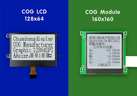
Modern embedded hardware faces tight power budgets and harsh outdoor environments. In 2026, battery-powered IoT nodes, solar energy storage inverters, and handheld diagnostic tools demand ultra-low standby power and instant wake-up visibility.
A TFT or OLED panel requires a constant frame buffer, high-speed MCU interfaces, and significant backlight or pixel current. A custom segment lcd display solves both challenges with a static or low-multiplex driver consuming as little as 5 to 20 microamps.
Two industry shifts define segment LCD selection in 2026:
Selecting the glass fluid and polarizer chemistry dictates contrast ratio, viewing angle, multiplex capability, and unit cost. Every custom monochrome lcd starts with choosing among five standard electro-optical modes.
TN glass uses a 90-degree molecular twist, as detailed in standard twisted nematic field effect physics. It offers the fastest response times and lowest unit cost, making it ideal for simple consumer thermometers and basic utility meters with 1 to 4 common lines.
HTN expands the molecular twist angle to roughly 100–120 degrees. This slight change widens the viewing cone and boosts contrast over TN glass while adding minimal cost.
STN rotates liquid crystal molecules between 180 and 270 degrees. This steep electro-optical curve supports high multiplex ratios (1/8 to 1/16 duty or higher), typically appearing in yellow-green, blue, or gray background modes.
FSTN adds a retardation compensation film to standard STN glass to cancel color dispersion. The result is crisp black-on-white or white-on-black contrast, making FSTN the workhorse for medical analyzers and precision test instruments.
VA glass aligns liquid crystal molecules perpendicular to the glass substrate when unpowered, blocking nearly all backlight leakage. Engineers select VA for premium smart home thermostats, automotive dashboards, and EV chargers requiring crisp icons and near-180-degree viewing symmetry.
| LCD Mode | Contrast Ratio | Viewing Angle | Max Practical Duty | Typical Operating Voltage | Relative Cost |
|---|---|---|---|---|---|
| TN | Low to Medium (10:1) | Narrow (45°–60°) | 1/1 to 1/4 | 3.0V – 5.0V | Lowest ($) |
| HTN | Medium (15:1) | Moderate (60°–80°) | 1/4 to 1/8 | 3.0V – 5.0V | Low ($+) |
| STN | Medium-High (20:1) | Wide (80°–110°) | 1/8 to 1/32 | 3.3V – 5.0V+ | Medium ($$) |
| FSTN | High (30:1+) | Wide (100°–120°) | 1/8 to 1/32 | 3.3V – 5.0V+ | Medium-High ($$+) |
| VA / BTN | Ultra-High (100:1+) | Full (160°–175°) | 1/1 to 1/8 | 3.3V – 5.0V | High ($$$) |
Glass chemistry alone does not determine outdoor readability on your custom segment lcd display. You must pair the cell with the right rear polarizer and illumination architecture.
Positive displays show dark segments on a light background and perform well with or without a backlight. Negative displays show bright, illuminated segments on a dark background.
Because negative displays absorb ambient light, they demand an always-on LED backlight when active. Keep that continuous 15mA to 40mA current draw in mind for battery-powered designs.
Side-lit LED backlights inject light into an acrylic light guide plate (LGP) using 1 to 4 surface-mount LEDs. This keeps the module thin (under 2.0mm backlight thickness) and uniform across large viewing areas.
Bottom-lit array backlights place multiple LEDs directly behind a diffuser sheet, delivering higher brightness for industrial equipment. Always include external current-limiting resistors or a constant-current driver on your host PCB to prevent LED thermal runaway.
Every segment on a custom glass panel sits at the intersection of a Common (COM) electrode and a Segment (SEG) electrode. Understanding LCD duty and bias calculation prevents dim segments and visual ghosting.
The maximum number of individually controllable segments equals the total number of COM pins multiplied by the total number of SEG pins. For example, an 8-digit 7-segment display with 8 decimal points needs 64 segments.
Driving 64 segments statically (1/1 duty) requires 64 SEG pins plus 1 COM pin—65 pins total. Switching to a 1/4 duty multiplex architecture uses 4 COM pins and only 16 SEG pins, cutting glass pin count from 65 down to 20.
Duty equals 1 / N, where N is the number of COM lines. Common ratios include 1/1 (static), 1/2, 1/3, 1/4, 1/8, and 1/16.
Bias equals 1 / B, defining the intermediate voltage steps used to keep unselected ("off") segments below the liquid crystal threshold voltage. To maximize the voltage margin between "on" and "off" pixels, use the standard optimal bias formula:
Optimal Bias Ratio = 1 / (√N + 1)
Mismatched bias or overly high duty ratios on TN glass cause cross-talk, also known as ghosting, where inactive segments faintly darken. Always verify that your host MCU's internal LCD controller supports your exact COM count and bias ladder.
TN, HTN, and STN displays exhibit asymmetric contrast depending on the viewing angle. Engineers specify the primary viewing direction using clock-face orientation:
Selecting the right interconnect defines how your custom segment lcd display integrates mechanically and electrically onto your main circuit board. You can source either bare ITO glass or a fully integrated LCD module.
When your host microcontroller includes an integrated LCD driver, bare glass keeps BOM costs minimal. Four interconnect options exist:
If your host MCU lacks enough LCD pins or you prefer communicating via I2C or SPI, choose an integrated driver module. Comparing a COG vs COB module comes down to space versus ruggedness:
At Chuanhang Display, you never have to split your supply chain between glass makers and assembly houses. Operating from a 5,000-square-meter production facility with over 100 skilled operators and a 10+ person R&D and sales engineering team, we run dedicated in-house COB, SMT, FOG, COG, and TFT lines. Whether you need raw custom glass or a turnkey module with integrated driver ICs and backlights, we control yield at every stage.
Clean CAD geometry prevents manufacturing defects and delays during ITO glass layout. Before sending drawings for tooling, verify these physical design rules.
Standard soda-lime LCD glass comes in 0.55mm, 0.7mm, and 1.1mm thicknesses. Thinner 0.55mm glass trims weight for wearables, while 1.1mm glass resists mechanical flexing in large 4-inch or 5-inch industrial panels.
Internal electrodes are etched onto a transparent indium tin oxide (ITO) conductive layer. Keep these layout margins in mind:
Outdoor instruments suffer polarizer yellowing and fluid degradation under ultraviolet exposure. Specify an anti-UV polarizer film for any device exposed to direct sunlight.
For harsh industrial floors, add ESD protection diodes on your host lines and verify glass edge grounding. All materials, solders, and backlights should comply with IEC environmental guidelines as well as global RoHS and REACH directives to clear customs in North American and European markets.
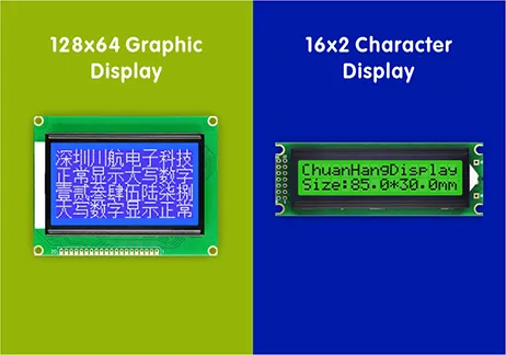
Moving a custom segment lcd display from CAD drawing to mass production follows a structured, low-risk timeline. Knowing each milestone helps hardware managers align PCB spins with display deliveries.
Q1: What is the typical tooling cost (NRE) and MOQ for a custom
segment lcd display?
A1: Standard bare glass
tooling typically ranges from $200 to $600 depending on glass size and layer
complexity, while integrated COG or COB modules with custom FPCs range from $800
to $2,000. Minimum order quantities (MOQ) usually start at 500 to 1,000 pieces
for mass production, though pilot batches are negotiable for industrial and
medical accounts.
Q2: How long does it take to receive custom prototypes after
confirming the engineering drawing?
A2: Standard
bare glass TN, HTN, STN, or FSTN prototypes take 12 to 18 business days after
drawing approval. Complex VA black-mask glass or custom modules requiring
bespoke FPC tooling and LED backlights typically ship within 3 to 4 weeks.
Q3: Can I change the backlight color or switch to negative mode
without paying for new glass tooling?
A3: Yes, in
most cases. Because the internal ITO electrode artwork remains identical,
changing the LED backlight color or swapping external polarizer films (such as
changing from positive gray to negative blue) usually requires zero new glass
tooling—only a minor sample validation fee.
Q4: How do I minimize power consumption on a 2026 battery-powered IoT
custom monochrome lcd?
A4: Choose a reflective TN
or HTN glass mode so you do not need a continuous backlight. Keep your multiplex
ratio low (1/1 static or 1/4 duty), select a 3.0V low-threshold liquid crystal
fluid, and operate the LCD driver at the lowest frame frequency (typically 32Hz
to 64Hz) that avoids visible flicker.
Q5: Should I connect my custom segment LCD directly to an MCU or use
an external driver IC?
A5: If your microcontroller
already includes an integrated LCD controller and enough free GPIO pins, direct
bare-glass connection lowers total BOM cost. If you are short on MCU pins,
operating over long board distances, or using a 1/8+ duty display, an external
driver IC (such as an HT1621 or PCF8576) in a COG or COB module simplifies PCB
routing via I2C or SPI.
Designing a dependable custom segment lcd display does not require guesswork. Locking in the right liquid crystal mode, bias math, and interconnect early protects your product schedule and keeps BOM costs lean.
Ready to move from schematic to hardware? Send your segment sketch, mechanical envelope, or target specs to the Chuanhang Display engineering team today for a complimentary DFM evaluation, optical recommendation, and 24-hour factory-direct quote.